Section 03-01B: Engine, 5.0L and 5.8L MFI | 1996 F-150, F-250, F-350 and Bronco Vehicles Equipped with 5.0L or 5.8L MFI Engines Workshop Manual |
DISASSEMBLY AND ASSEMBLY
Subassemblies
Cylinder Head
Disassembly
Remove the exhaust manifolds and the spark plugs (12405).
Clean the carbon out of the cylinder head combustion chambers before removing the valves.
Carefully compress the valve spring (6513) using a suitable valve spring compressor. Remove the valve spring retainer key (6518) and release the valve spring.
Remove the sleeve, spring retainer or retainer/rotator, valve spring, guide mounted stem seal and valve. Discard the valve stem seal (6571). Identify all valve parts.
Clean, inspect and repair the cylinder head as required, or transfer all usable parts to a new cylinder head.
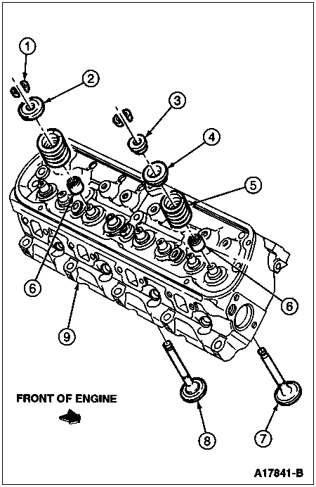
| Item | Part Number | Description |
|---|
| 1 | 6518 | Valve Spring Retainer Key |
| 2 | 6514 | Valve Spring Retainer (Exhaust Only) |
| 3 | 6517 | Valve Spring Retainer Sleeve (Intake Only) |
| 4 | 6514 | Valve Spring Retainer (Intake Only) |
| 5 | 6513 | Valve Spring |
| 6 | 6571 | Valve Stem Seal (White, Intake Only) |
| 7 | 6507 | Intake Valve |
| 8 | 6505 | Exhaust Valve |
| 9 | 6049 | Cylinder Head |
Assembly
Install each valve in the port from which it was removed or to which it was fitted. Install a new valve stem seal on the intake valve guide and exhaust valve guide.
Install the valve spring over the valve, and then install the spring retainer and sleeve. Compress the valve spring using a suitable valve spring compressor and install the valve spring retainer keys.
 CAUTION: Do not install the spacers unless necessary. Use of spacers in excess of recommendations will result in overstressing the valve springs and overloading the camshaft lobes which could lead to valve spring breakage and worn camshaft lobes.
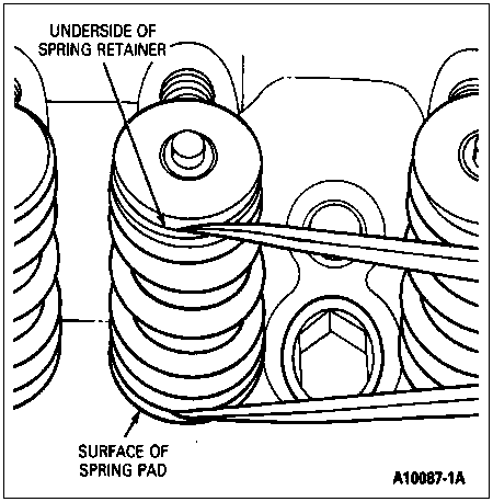
Measure the assembled height of the valve spring from the surface of the cylinder head spring pad to the underside of the spring retainer with dividers. Check the dividers against a scale. The spring assembled heights should measure 1.78 inch for intake and 1.60 inch for exhaust. If the assembled height is greater than specifications, install the necessary 0.762mm (0.030-inch) thick spacer(s) between the cylinder head spring pad and the appropriate valve spring to bring the assembled height to the recommended height.
Install the exhaust manifolds and the spark plug.
Pistons, Piston Pins and Rings
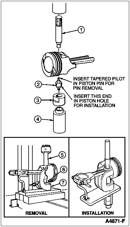
SPECIAL SERVICE TOOL(S) REQUIRED| Description | Tool Number |
|---|
| Piston Pin Remover/Replacer | T68P-6135-A |
Disassembly
Remove the bearing inserts from the connecting rod and cap.
Mark the pistons to make sure they are assembled with the same rod and installed in the same cylinders from which they were removed.
Using an arbor press and the Piston Pin Remover/Replacer T68P-6135-A, press the piston pin from the piston and connecting rod. Remove the piston rings if they are to be replaced.
Piston Pin, Removal and Installation
| Item | Part Number | Description |
|---|
| 1 | — | Driver (Part of T68P-6135-A) |
| 2 | — | Locator
(Part of T68P-6135-A) |
| 3 | — | Adapter
(Part of T68P-6135-A) |
| 4 | — | Cup (Part of T68P-6135-A) |
| 5 | — | Pin Pusher
(Part of T68P-6135-A) |
| 6 | 6135 | Piston Pin |
| 7 | — | Receiving Tube
(Part of T68P-6135-A) |
Assembly
The piston, connecting rod and related parts are shown. Check the fit of a new piston in the cylinder bore before assembling the piston and piston pin to the connecting rod.
The piston pin bore of a connecting rod and the diameter of the piston pin must be within specifications. Refer to Specifications in this section.
NOTE: Replacement pistons are slightly lighter in weight. Pistons must be replaced as a complete set to avoid the introduction of torsional vibration to the engine.
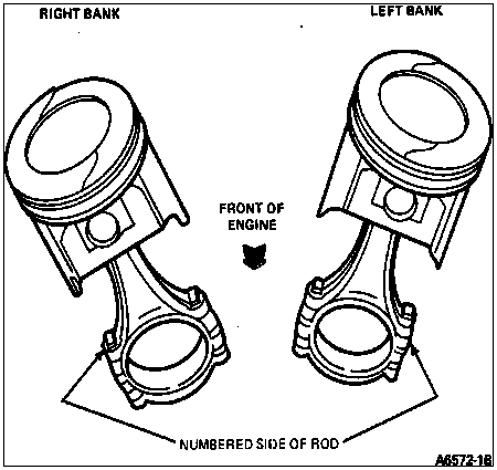
NOTE: Assemble the piston to the connecting rod with the indentation in the piston positioned as shown.
Apply a light coat of recommended quality engine oil to all parts.
On replacement connecting rods, install the large-chamfered side of the connecting rod bearing bore toward the crankshaft cheek; facing toward front of engine on the right bank rods, and facing toward rear of engine on left bank rods.
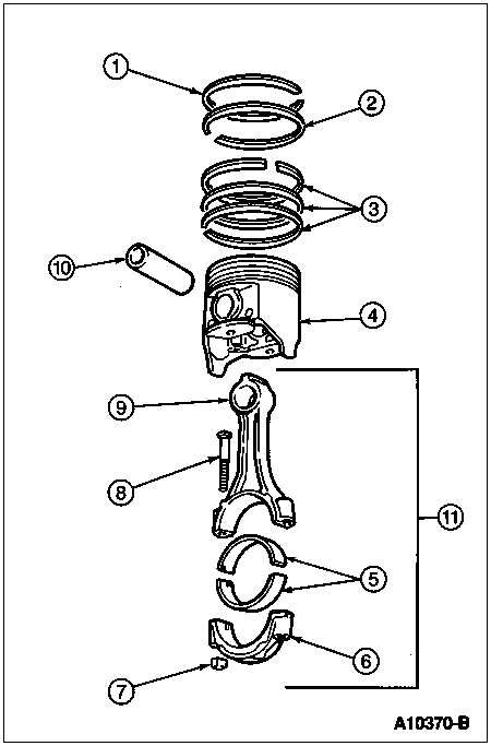
| Item | Part Number | Description |
|---|
| 1 | 6148 | Partial Piston Ring Set (Upper) |
| 2 | 6148 | Partial Piston Ring Set (Lower) |
| 3 | — | Oil Ring (Part of 6148) |
| 4 | 6102 | Piston, Pin and Ring |
| 5 | 6211 | Connecting Rod Bearing |
| 6 | 6210 | Cap — Connecting Rod |
| 7 | 6212 | Connecting Rod Nut |
| 8 | 6214 | Connecting Rod Bolt |
| 9 | 6200 | Connecting Rod |
| 10 | 6135/6108 | Piston Pin/Piston and Pin Assembly |
| 11 | — | Connecting Rod and Rod Bearings (Part of 6200) |
Start the piston pin in the piston and connecting rod (this may require a very light tap with a mallet). Using an arbor press and Piston Pin Remover/Replacer T68P-6135-A, press the piston pin through the piston and connecting rod until the pin is centered in the piston.
Check the end gap of all piston rings. Refer to Section 03-00. It must be within specifications. Follow the instructions contained on the piston ring package and install the piston rings using a piston ring installation tool of the proper size.
NOTE: If the lower lands have high steps, the piston should be replaced.
Check the ring side clearance of the compression rings with a feeler gauge inserted between the ring and its lower land. Refer to Section 03-00. The gauge should slide freely around the entire ring circumference without binding. Any wear that occurs will form a step at the inner portion of the lower land.
Make sure the bearing inserts and the bearing bore in the connecting rod and cap are clean. Foreign material under the inserts will distort the connecting rod bearing and cause a failure. Install the connecting rod bearing inserts in the connecting rod and cap with the tangs fitting in the slots provided.
Oil Pump
Disassembly
Remove the oil pump screen cover and tube from the oil pump and remove the gaskets.
Remove the cover attaching bolts, then remove the cover. Remove the inner rotor and shaft assembly. Then remove the outer race.
Drill a small hole and insert a self-threading sheet metal screw of the proper diameter into the oil pressure relief valve chamber cap and pull the cap out of the chamber. Remove the spring and plunger.
| Item | Part Number | Description |
|---|
| 1 | — | Bolt (Part of 6600) |
| 2 | 6666 | Oil Pump Relief Valve Plug |
| 3 | 6670 | Oil Pump Relief Valve Spring |
| 4 | 6614 | Oil Pump Relief Valve Repair Kit |
| 5 | 6600 | Oil Pump |
| 6 | — | Bolt (Part of 6600) |
| 7 | — | Identification Mark |
| 8 | — | Bolt (Part of 6600) |
| 9 | 6616 | Oil Pump Body Plate |
| 10 | 6608 | Oil Pump Drive Rotor and Shaft |
| 11 | 6626 | Oil Pump Inlet Tube Gasket |
| 12 | 6622 | Oil Pump Screen Cover and Tube |
| A | — | 5.8L, Tighten to 14-20 Nm
(10-15 Lb-Ft)
5.0L, Tighten to 12-18 Nm
(9-13 Lb-Ft) |
| B | — | Tighten to 30-43 Nm
(22-32 Lb-Ft) |
Assembly
Clean, inspect and oil all parts thoroughly.
Install the oil pressure relief valve plunger, spring and a new cap.
NOTE: Be sure the dimple (identification mark) on the outer race is facing the same side as the identification mark on the rotor.
Install the outer race and the inner rotor and shaft assembly.
Replace gasket and install the cover and tighten the cover attaching bolts to 30-43 Nm (22-32 lb-ft).
Valve Tappet, Hydraulic
The internal parts of each hydraulic tappet assembly are matched sets. Do not mix the parts. Keep the assemblies intact until they are to be cleaned.
Valve tappets should always be tested after assembly. Refer to Section 03-00.
Disassembly
Disassemble and assemble each valve tappet separately. Keep the valve tappets in proper sequence so that they can be installed in their original bores.
Grasp the plunger retainer with needlenose pliers to release it from the groove. It may be necessary to depress the leakdown plunger to fully release the plunger retainer.
Remove the push rod socket, metering valve (disc), plunger and spring.
Carefully remove the plunger spring, the check valve retainer socket, the check valve spring and valve from the plunger.
Roller Tappet, 5.0L/5.8L Engines
| Item | Part Number | Description |
|---|
| 1 | — | Cam Roller (Part of 6500) |
| 2 | — | Needles (Part of 6500) |
| 3 | — | Axle (Part of 6500) |
| 4 | — | Plunger Spring (Part of 6500) |
| 5 | — | Check Ball Spring
(Part of 6500) |
| 6 | — | Ball Retainer (Part of 6500) |
| 7 | — | Check Ball (Part of 6500) |
| 8 | — | Leak-Down Plunger
(Part of 6500) |
| 9 | — | Plunger Retainer
(Part of 6500) |
| 10 | — | Plunger Retainer
(Part of 6500) |
| 11 | — | Body (Part of 6500) |
Assembly
Place the plunger upside down on a clean workbench.
Place the check valve (disc or check ball) in position over the oil hole on the bottom of the plunger. Set the check valve spring on top of the check valve (disc or check ball).
Position the check valve retainer over the check valve and spring and push the retainer down into place on the plunger.
Place the plunger spring, and then the plunger (open end up) into the valve tappet body.
Position the metering valve (disc) in the plunger and then place the push rod socket in the plunger.
Depress the plunger, and position the closed end of the plunger retainer in the groove of the valve tappet body. With the plunger still depressed, position the open ends of the plunger retainer in the groove. Release the plunger, and then depress it again to fully seat the plunger retainer.
Use the Tappet Leakdown Tester TOOL-6500-E to fill the valve tappets with test fluid. Refer to Section 03-00.
Cylinder Block Assembly
Disassembly
Mount the engine in a workstand and remove all parts not furnished with the new cylinder block assembly following engine components removal and installation procedures in this section.
Remove the cylinder block assembly from the workstand.
Assembly
CAUTION: Do not use solutions such as brake cleaner, carburetor cleaner, etc., as these solutions can leave a residue on the machined surfaces. Use only a cleaner which meets or exceeds Ford specification WSE-M5B392-A, such as Metal Surface Cleaner F4AZ-19A536-RA or equivalent.
Clean the gasket and seal surfaces of all serviceable parts and assemblies.
Position the new cylinder block assembly in a workstand.
Transfer all serviceable parts removed from the old cylinder block assembly following removal and installation procedures in this section.
Check all assembly clearances following Specifications listed at the end of this section, and correct as necessary.
Cylinder Block, Bare
Before replacing a cylinder block, determine if it is repairable. If so, make the necessary repairs. Refer to Section 03-00.
Disassembly
Completely disassemble the engine. Refer to Engine in the Disassembly and Assembly portion of this section.
Ridge-ream the cylinder bores before removing piston assemblies.
Assembly
Clean the gasket and seal surfaces of all serviceable parts and assemblies.
Position the new cylinder block in a workstand.
Transfer all serviceable parts removed from the old cylinder block following appropriate removal and installation procedures in this section.
Check all assembly clearances. Refer to Specifications and correct as necessary.