Section 05-02G: Axle, Integral Carrier, 8.8-Inch Ring Gear
1996 F-150 and Bronco Workshop Manual
REMOVAL AND INSTALLATION

Sensor Ring, Anti-Lock Speed


Removal

  1. Raise vehicle and install safety stands.

  1. Remove rear wheels and tires. Refer to Section 04-04.

  1. Remove rear brake drums (1126). Refer to Section 06-02.

  1. Remove rear axle housing cover (4033). Refer to Cover in the Removal and Installation portion of this section.

  1. Remove both rear axle shafts (4234).

  1.  CAUTION: Bearing caps MUST NOT be interchanged or rotated.

    NOTE: The direction and location of triangles on bearing caps must be noted. When reassembled, the triangles must be pointing in the same direction (outboard) as before removal.

    Mark one differential bearing cap to make sure the caps will be installed in their original locations and positions with triangles pointing outboard.

  1. Loosen the differential bearing cap bolts and bearing caps.

  1.  CAUTION: When using the pry bar in the following step, place a wood block between the pry bar and the axle housing to protect the differential carrier face from damage.

    Pry the differential case (4204), differential bearing cups (4222) and differential bearing shims (4067) out until they are loose in the bearing caps. Remove the bearing caps and remove the differential case from the carrier.

  1. Remove the bolts that attach the ring gear to the differential case. Remove the ring gear from the differential case by striking at alternate holes around the gear. Use a punch that is small enough to hit the bottom of the tapped holes and not damage the threads. Use care to prevent damage to ring gear teeth. Support the ring gear while removing the bolts so the ring gear does not fall and nick any teeth.

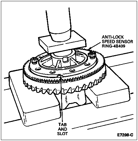
  1. Remove the anti-lock speed sensor ring with a soft-faced hammer and discard. Once removed, the anti-lock speed sensor ring cannot be reused. A new anti-lock speed sensor ring must be installed.


Installation

  1.  CAUTION: Extreme care should be taken not to scratch, dent, chip or otherwise cause damage to speed sensor ring or teeth while handling or during assembly.

    Align tab on anti-lock speed sensor ring with slot in differential case. Tab on anti-lock speed sensor ring MUST be aligned with slot in differential case. Start two ring gear bolts through the differential case into the ring gear to ensure case-to-ring gear bolt hole alignment.

    ItemPart NumberDescription
    143114-S100Ring Gear Bolts
    24B409Anti-Lock Speed Sensor Ring
    34209Ring Gear
    4Anti-Lock Speed Sensor Ring Tab (Part of 4B409)
    5Differential Case Slot (Part of 4204)
  1. Press the anti-lock speed sensor ring on the differential case using the ring gear as a pilot. Apply Threadlock® and Sealer EOAZ-19554-AA or equivalent meeting Ford specification WSK-M2G315-A5 to ring gear bolts.

  1. Install ring gear bolts and tighten to 95-115 Nm (70-85 lb-ft).

  1. Install differential case in carrier.

  1. Install a 6.73mm (0.265-inch) shim on left side.

  1. NOTE: Triangles on bearing cups must point outboard.

    NOTE: When installing, apply pressure toward left side to make sure the left bearing cup is seated.

    Install left bearing cap and tighten bolts finger-tight.

  1. Install shim to right side while applying pressure toward left side.

  1. Install right side bearing cap and tighten bolts to 95-115 Nm (70-85 lb-ft).

  1. Check backlash and runout. Adjust if necessary. Refer to Differential Case Installation in the Disassembly and Assembly portion of this section.

  1. Install both rear axle shafts.

  1. Install rear axle housing cover. Refer to Cover Installation in this section.

  1. Install rear brake drums. Refer to Section 06-02.

  1. Install rear wheels and tires. Refer to Section 04-04.

  1. Check and add fluid (rear axle). Refer to Lubricant Capacities in the Specifications portion of this section.

  1. Remove safety stands and lower vehicle.

  1. Road test.