Section 07-07A: Transfer Case, Electronic Shift
1996 F-150 4x4 Vehicles with Automatic Transmissions and All Bronco Vehicles Workshop Manual
DISASSEMBLY AND ASSEMBLY

Transfer Case, Electronic Shift

SPECIAL SERVICE TOOL(S) REQUIRED
DescriptionTool Number
Seal RemoverT74P-77248-A
Impact Slide HammerT50T-100-A
Bearing Cup ReplacerT73T-1202-B
Driver HandleT80T-4000-W
Bearing Cup ReplacerT80T-4000-P
Output Shaft Seal ReplacerT86T-7034-CH

Disassembly

  1. Remove the transfer case (7A195) from the vehicle as outlined in this section.

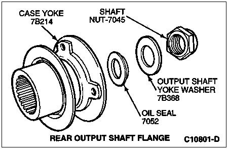
  1. Remove the front and rear case yokes (7B214) by removing the 32mm shaft nut (7045), output shaft yoke washer (7B368), oil seal (7052) and yoke to flange seal (7B215) from the output shafts.

    13-56 Transfer Case, Electronic Shift

    ItemPart NumberDescription
    1Cap, Bearing/Extension (Serviced As Part of 7085 Assembly)
    27B215Yoke to Flange Seal
    37052Oil Seal
    47045Shaft Nut
    57B368Output Shaft Yoke Washer
    6Yoke (Rear Yoke) (Serviced As Part of 7B214 Assembly)
    Flange (Rear Flange) (Serviced As Part of 7B214 Assembly)
    7Deflector (Serviced As Part of 7B214 Assembly)
    87B214Case Yoke
    97A443Bolt and Washer Assembly (1989 and Later)
    107085Bearing Retainer
    117A247/7288Sensor and O-Ring Assembly
    127A247Sensor, Speed
    137288O-Ring
    14Bolt (Part of 7G360)
    15Bolt (Part of 7G360)
    167G360Transfer Case Shift Motor
    17Bolt (Part of 7A195)
    1814A206Wire Connector Bracket
    197A010Plug, Pipe
    207A443Bolt
    217917Ring, Snap
    227025Bearing
    23620481-SNut
    247288Shifter Shaft Seal
    257W073Bushing, Sleeve
    267005Case (Rear)
    277127Caged Needle Bearing
    287G361Coil Assembly, Clutch
    297917Ring, Snap
    307005Case (Rear Assembly)
    317A149/7061Shaft and Pump Assembly
    327061Output Shaft
    337A250Pin, Pump
    347A205Spring, Pump Pin
    357A250Pin, Pump
    36382486-SClamp, Hose
    377A152Cover, Pump, Front
    387A149Housing, Pump
    397A152Cover, Pump, Rear
    407E215Retainer, Pump
    417A210Hose
    427A291Bolt, Hex-Head
    437A098Filter, Oil
    447177Sprocket, Drive
    457106Lockup Collar
    467D126Spring, Lockup
    477D164Lockup Hub
    487917Ring, Retaining
    49Hub, Shift (Part of 7G362)
    507G362Housing, Clutch
    517106Lockup Assembly, 2W-4W
    527100Shift Collar Hub
    537A398Front Planet
    547C122Ring, Retaining
    557A153Ring Gear
    567917Ring, Retaining
    577025Bearing
    587917Ring, Retaining
    597B215Yoke to Flange Seal
    607034Vent
    617B214Case Yoke
    627045Shaft Nut
    637B368Output Shaft Yoke Washer
    647052Oil Seal
    65Yoke (Serviced As Part of 7B214 Assembly)
    66Deflector (Serviced As Part of 7B214 Assembly)
    677289Fork Assembly, Reduction
    68Pin, Roller and Retainer Assembly (Serviced As Part of 7289 Assembly)
    69Pin (Serviced As Part of 7289 Assembly)
    70Roller, Cam (Serviced As Part of 7289 Assembly)
    71Retainer (Serviced As Part of 7289 Assembly)
    72Fork, Reduction (Serviced As Part of 7289 Assembly)
    73Facing, Shift Fork (Serviced As Part of 7289 Assembly)
    74Facing, Shift Fork
    (Part of 7289)
    757289Fork Assembly, Shift, 2W-4W
    767240Shift Rail
    7772192W-4W Shift Fork Spring
    787F063Cam, Electric Shift
    797W074Spring, Torsion
    807Z112Spacer
    817N095Shaft, Shift
    827917Ring, Retaining
    837119Thrust Washer
    847A029Chain, Drive
    857177Sprocket, Drive
    867061Output Shaft
    877917Ring, Retaining
    887025Bearing
    89Pin Dowel (Part of 7005)
    907005Case (Front)
    917B215Yoke to Flange Seal
    927005Case (Front Assembly)
    937L027Oil Pan Magnet
  1. Remove the rear yoke to flange seal using Seal Remover T74P-77248-A and Impact Slide Hammer T50T-100-A.

  1. Remove the wire connector from the mounting bracket on the rear cover. If required, remove the two bolts and remove the bracket.

  1.  CAUTION: Do not damage the wire connector locking sleeve.

    Form a small hook from the end of a paper clip. Remove the locking sleeve from the wire connector by hooking it with the paper clip and pulling it up from the bottom.

  1. Remove the brown wire from the No. 1 center position in the connector. If required, remove the green speed sensor wire from the No. 4 connector position and the blue wire from the No. 5 connector position.

  1.  CAUTION: When removing the RTV sealant, use care not to damage the mating surfaces of the cases (7005).

    Remove the four No. 50 Torx® head bolts securing the rear bearing retainer to the case. Pry the rear bearing retainer from the case using a 1/2-inch drive breaker bar between the pry bosses and separate the bearing retainer from the case. Remove all traces of RTV Gasket Sealant from the mating surfaces of the case and the bearing retainer.

    Transfer Case, Rear View

    ItemPart NumberDescription
    17G360Transfer Case Shift Motor
    27A443Bolt
    37085Bearing Retainer
    47005Case
  1. Remove the speed sensor from the rear case.

  1.  CAUTION: The motor is serviced as a complete assembly. Do not remove the screws that secure the rear case to the motor gear housing.

    Remove the four bolts attaching the shift motor to the rear case and remove the shift motor. Note the position of the triangular shaft extending out of the rear case and the triangular slot in the motor. Do not discard the washer under the motor support bracket, if present.

  1. Remove the snap ring on the output shaft retaining the upper rear bearing (7025), using appropriate snap ring pliers as shown.

    ItemPart NumberDescription
    17061Output Shaft
    27025Bearing
    37005Case
    47917Snap Ring
  1.  CAUTION: When removing the RTV sealant, use care not to damage the mating surfaces of the housings.

    Remove the 12 No. 50 Torx® head bolts that retain the front case and the rear case. Insert a 1/2-inch drive breaker bar between the pry bosses and separate the front case from the rear case. Remove all traces of RTV Gasket Sealant from the mating surfaces of the front case and the rear case.

  1. Remove the front output shaft caged needle bearing from the rear case with Collet D80L-100-T (from Blind Hole Puller Set D80L-100-A or equivalent) and Impact Slide Hammer T50T-100-A.

  1. Remove the rear output shaft bearing from the inside of the case using a suitable tool.

    Rear Cover Assembly

  1. Remove the nuts retaining the clutch coil to the rear case. Pull the assembly, along with the O-rings and brown wire, from the case.

  1. Remove the shift shaft rail socket bushing and seal from the rear case using appropriate tools.

  1. Remove the snap ring on the output shaft securing the clutch housing. Slide the clutch housing and the lockup hub off of the output shaft.

  1. Remove the 2W-4W shift fork spring from the shift shaft and lift the mode shift fork, complete with the lockup collar hub, from the upper rear output shaft sprocket splines.

  1. Disassemble the 2W-4W lockup assembly by removing the internal snap ring and pull the lockup hub and spring from the lockup collar hub.

  1. Remove the snap ring retaining the driven sprocket to the front output shaft. Grasp the drive and driven sprocket, complete with the chain, and lift them at the same time from the rear and front output shafts.

  1. Remove the shift rail by sliding it straight out from the shift fork.

  1. Remove the oil pan magnet (7L027) from its slot in the case.

  1.  CAUTION: Do not disassemble oil pump unless the oil pump retaining bracket has been bent or broken, or pump damage is indicated. Indications of pump failure are blueing or blackening of the pump, or loosening of the pump bolts.

    Lift out the pump screen and remove the output shaft with the pump assembled on it. If the pump is to be disassembled, remove the four bolts from the pump body. Note the position of the pump front body, pins, spring, rear cover and pump retainer as removed.

    Rear Output Shaft and Oil Pump Assembly

    ItemPart NumberDescription
    17A149Pump Body
    27A152Cover
    37A205Spring
    47A250Pins
    57A098Pick-Up Tube and Filter
    67A152Cover
    77061Output Shaft
    87A291Bolts, Hex-Head
  1. Remove the high-low shift fork by first rotating it until the roller is free from the cam, then sliding it out of engagement from the shift collar.

  1.  WARNING: THE SPRING IS UNDER LOAD AND MAY RELEASE VIOLENTLY.

    Remove the helical cam from the front case. If it is necessary to disassemble the helical cam, care should be exercised as the cam is slid rearward to disengage it from the spring. The spring must be removed from the helical cam and the shaft finger. Do not get your fingers in the way when disengaging the spring. It will rotate to the point that the spring ends will be roughly 180 degrees apart.

  1. Remove the shift collar.

  1. Remove the front output shaft from the front case.

  1. Turn the front case over and remove the front output and input yoke to flange seals out of the case, using Seal Remover T74P-77248-A and Impact Slide Hammer T50T-100-A.

  1. Reaching through the front opening of the case with a pair of snap ring pliers, expand the snap ring on the input shaft and carrier assembly allowing it to drop out of the bearing. The carrier assembly, including the input shaft, is serviced as an assembly only. If the needle bearing or bushing is to be replaced in the input shaft (7017), drive out both of them through the input shaft splines using appropriate tools.

  1. Remove the ring gear (7A153) by prying out the internal snap ring and lifting out the ring gear.

  1. Remove the front input shaft bearing by removing the internal snap ring securing the bearing to the case and driving it out from the outside of the case using Bearing Cup Replacer T73T-1202-B and Driver Handle T80T-4000-W.

  1. Remove the front output shaft bearing from case by removing the internal snap ring retaining the bearing in the case. Drive the bearing out of the case from the front of the case using Bearing Cup Replacer T73T-1202-B and Driver Handle T80T-4000-W.

Assembly

  1. NOTE: Before assembly, lubricate all parts with Motorcraft MERCON® automatic transmission fluid ATF XT-2-QDX or equivalent.

    Clean all chips out of the case attaching bolt holes. Install the input shaft bearing and the front output shaft bearing into the case using Bearing Cup Replacer T80T-4000-P and Driver Handle T80T-4000-W. Install the appropriate internal snap rings retaining the bearings in the case.

  1. Install the front output shaft yoke to flange seal into the case until it is fully seated against the case using Output Shaft Seal Replacer T86T-7034-CH.

  1. Install the front output shaft through the lower bearing of the case. The front output shaft is retained in the case by the front yoke to flange seal. Install the front case yoke onto the output shaft, the oil seal, the output shaft yoke washer, and the shaft nut. Tighten shaft nut to 162-203 Nm (120-150 lb-ft).

  1. Press the needle bearing and bronze bushing into the input shaft with the appropriate tools.

  1. Install the ring gear into the slots in the case and retain it with the large internal snap ring making sure that it is fully seated.

  1. Insert the input shaft and front planet (7A398) in the case through the input shaft bearing being careful not to damage the gear teeth when aligning them with the ring gear teeth.

  1. While supporting the input shaft and front planet in the case,install a new snap ring on the front side of the bearing making sure that it is fully seated in the snap ring groove of the input shaft.

  1. Install the input shaft yoke to flange seal into the case using an appropriate tool until it is fully seated against the case.

  1. Reassemble the helical cam by engaging one end of the spring on the shaft finger and the other end of the spring on the cam finger. With the shaft finger secured carefully in a soft-jawed vice, turn the cam to wind up the spring until the fingers of the cam and the shaft are in alignment and slide the cam forward to lock the spring in the cocked position.

  1. Install the cam in the small hole of the case with the shaft vertical.

  1. Lubricate all pump components with clean automatic transmission fluid.

  1. Reassemble pump and output shaft as follows:

    1. Place the oil pump cover, with the word "TOP" facing the front of the front case, on the output shaft.
    1. Install two pins (with the flats facing the rear of vehicle) with the spring between the pins in the oil pump bore in the output shaft.
    1. Place the oil pump body and pick-up tube over the output shaft and make sure that the pins are riding against the inside of the pump body.
    1. NOTE: The word "TOP" on the front cover and the rear cover should be pointing in the same direction.

      Place the oil pump rear cover with the words "TOP REAR" facing the rear of the case on the output shaft.
    1. Install the pump retainer with the tabs facing the front of the transfer case.
    1. NOTE: The output shaft must turn freely within the oil pump. If binding occurs, loosen the four screws and retighten.

      Install the four retaining screws and rotate the output shaft while tightening the screws to prevent the pump from binding. Tighten the screws to 4-4.5 Nm (35-40 lb-in).
  1. Install the shift collar.

  1. Install the high-low shift fork by engaging it with the shift hub flange and rotating it until the roller is engaged with the lower groove of the helical cam.

  1. Install the shift rail through the high-low fork bore and into the rail bore in the case.

  1. NOTE: Make sure that the external splines of the output shaft engage the internal splines of the shift hub. Make sure that the oil pump retainer and oil filter leg are in the groove and notch of the front case.

    Install the output shaft and oil pump in the input shaft.

  1. Install oil pan magnet in the slot provided in the front case.

  1. Assemble the following components:

    1. Assemble the drive sprocket into the chain.
    1. NOTE: The sprocket engagement spline will face the rear of the vehicle when properly installed.

      Assemble the driven sprocket into the chain so the word REAR is facing upward.
    1. Place the sprockets and chain as an assembly over the rear and front output shafts.
    1. Install the thrust washer (7119) and snap ring that retains the lower sprocket to the front output shaft.

  1. Assemble the 2W-4W lockup as follows:

    1. Position the small end of the tapered compression spring in the lockup collar hub.
    1. NOTE: The snap ring holds the lockup together.

      Place the lockup hub over the large end of the spring and compress the spring while installing the internal snap ring.

  1. Install the lockup and its shift fork over the external splines of the sprocket and the shift rail with the clutch face facing rearward and the cam follower feature of the fork facing the front of the transfer case.

  1. Assemble the 4WD return spring over the shift rail and against the shift fork.

  1. Place the clutch housing over the splines of the output shaft and secure with the appropriate snap ring. Make sure that the snap ring is fully seated in the snap ring groove.

    Installation, Shift Mechanism

    ItemPart NumberDescription
    17177Front Output Shaft Driven Sprocket
    27289High-Low Shift Fork
    37N095Helical Cam
    47219Lockup Spring
    57061Output Shaft (Rear)
    67G362Clutch Housing
    772892W/4W Drive Shift Fork
    87240Shift Rail
    97A029Drive Chain
  1. Press the front output shaft inner needle bearing in the bore in the rear case using appropriate tools.

  1. Press the rear output shaft bearing into the bore in the rear case using appropriate tools.

  1. Install a new shift shaft bushing and oil seal into the rear case using appropriate tools.

  1.  CAUTION: Do not kink or trap the wire while seating the clutch coil on the case.

    Install new O-rings (if the old rings are cracked or broken) on the clutch coil studs and grommet. Install the clutch coil from inside the rear case until the wire and studs extend through the case. Install the three nuts and tighten to 8-11 Nm (70.8-97.4 lb-in).

  1. Install the rear output case yoke in the bearing retainer using the appropriate tool, and make sure that it is fully seated.

  1.  CAUTION: If too much silicone rubber is used when sealing the case halves, it is possible for the excess sealant to plug the oil filter and cause transfer case failure.

    Coat the mating surface of the front case with a very small bead of black non-acid cure Silicone Rubber E7TZ-19562-A or equivalent meeting Ford specification ESL-M4G273-A.

  1.  CAUTION: Do not use bolts that do not have a plastic coating on the head. If the plastic coating on the bolts has peeled or cracked, replace them with new bolts that have coating intact.

    Fit the case halves together making sure that the lower output shaft, shift shaft and shift rail are aligned. Install and tighten the 12 No. 50-Torx® bolts to 35-43 Nm (26-32 lb-ft).

  1. Install the rear bearing snap ring on the output shaft, making sure that the snap ring is fully seated in the groove of the output shaft.

  1. Install the speed sensor in its bore on the case.

  1. Apply a bead of non-acid cure Silicone Rubber, E7TZ-19562-A or equivalent meeting Ford specification ESL-M4G273-A to the face of the rear bearing retainer.

  1.  CAUTION: Do not trap the brown wire beneath the bearing retainer.

    Place the rear bearing retainer onto the rear case and secure with the four Torx® head bolts (7A443) tightened to 35-43 Nm (26-32 lb-ft).

  1. Install the rear output case yoke onto the rear splines of the output shaft. Install the oil seal, output shaft yoke washer and 32mm shaft nut on the output shaft and tighten to 162-203 Nm (120-150 lb-ft).

  1. Using pliers equipped with soft jaws, rotate the triangular shift shaft so it is aligned with the triangular slot in the motor.

  1. NOTE: Do not loosen the two nuts or studs that attach the motor end cap to motor housing.

    Slightly loosen the two nuts that attach the slotted support bracket to the end of motor house.

  1. Apply black non-acid cure silicone rubber E7TZ-19562-A or equivalent meeting Ford specification ESL-M4G273-A to motor housing base and install on transfer case.

  1. Install three screws along with speed sensor bracket and tighten to 8-11 Nm (70.8-97.4 lb-in).

  1. Holding the slotted support bracket tight against the motor housing end, secure the bracket to the transfer case, turning the lockwasher to 8-11 Nm (70.8-97.4 lb-in).

  1. NOTE: If the shaft will not stay in the 4H position, rotate the shaft clockwise to the 2H position. Install the motor and rotate counterclockwise until the motor is aligned with the mounting holes.

    Retighten the two nuts that attach the slotted support bracket to the end of motor to 2.7-3.4 Nm (24-30 lb-in).

  1. Install the brown clutch coil wire to the No. 1 center terminal, and, if removed, the speed sensor green wire to the No. 4 connector position and the blue wire to the No. 5 connector position. Install the locking sleeve.

  1. Install the wire connector bracket on the rear case. Install the bolts and tighten to 8-11 Nm (70.8-97.4 lb-in).

  1. Install the wire connector to the wire connector bracket.

  1. Install the drain plug and tighten to 9-23 Nm (7-17 lb-ft).

  1. Install the transfer case as described in the Removal and Installation portion of this section.

  1. Place a 3/8 inch drive ratchet in the fill plug and remove the plug. Fill the transfer case with 1.9 liters (2.0 U.S. quarts) of Motorcraft MERCON® automatic transmission fluid ATF XT-2-QDX or equivalent.

  1. Install the fill plug and tighten to 9-23 Nm (7-17 lb-ft).