Section 01-04: Pickup Box
1996 F-150, F-250, F-350 Regular and SuperCab Workshop Manual
ADJUSTMENTS

Shimming, Pickup Box

 
  1. Loosen all box attaching bolts. Remove the four bolts on the low side of the box.


    Pickup Box Bolt Locations
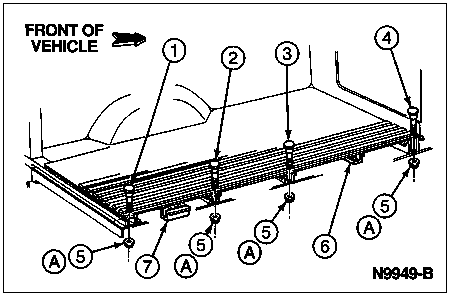


    ItemPart NumberDescription
    1N803022-S40Bolt, M12-1.75 x 88.9
    (No. 4 Box Bolt)
    2N803020-S40Bolt, M12-1.75 x 76.2
    (No. 3 Box Bolt)
    3N803020-S40Bolt, M12-1.75 x 76.2
    (No. 2 Box Bolt)
    4N803023-S40Bolt, M12-1.75 x 10⁸
    (No. 1 Box Bolt)
    5N620483-S2Nut
    6—Sill (8-Ft. Box Only)
    (No. 2 Sill) (Part of 11215)
    7—Sill (No. 5 Sill)
    (Part of 11215)
    A—Tighten to 54-95 Nm
    (40-70 Lb-Ft)
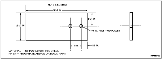
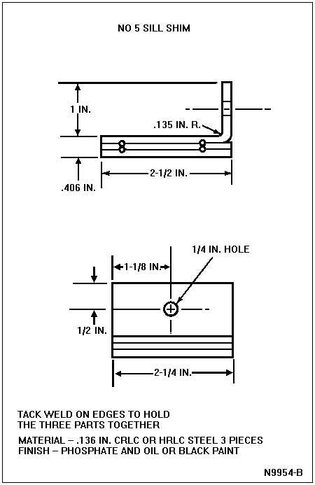
  1. Raise the low side of the box and insert the shims between the top of the frame and bottom of the box cross sills according to the following chart.


  1. NOTE: Bolts should be held down from top of box to prevent the shoulder from popping out of the floor while starting the nut. Tighten all bolts to 54-95 Nm (40-70 lb-ft).

    Install the bolts listed in Specifications portion of this section on the side of the box that was shimmed and tighten all box bolt nuts to 54-95 Nm (40-70 lb-ft).


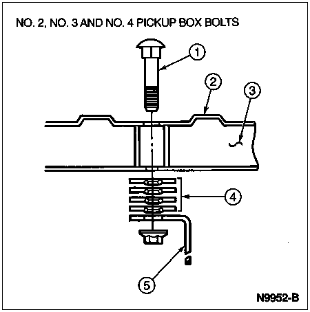
    ItemPart NumberDescription
    1N803022-S40Box Bolt
    211215Pickup Box Floor Pan
    3—Pickup Box Sill
    (Part of 11215)
    4N803334-S2Shims, 2.5 Inch O.D. x .75 I.D. x .060 (Quantity Changes with Location)
    55005Chassis Frame


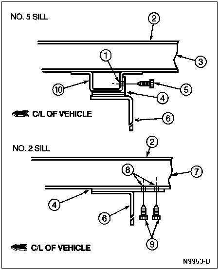
    ItemPart NumberDescription
    1—Drill 3/16 Inch Pilot Hole, in Steady Rest
    2—Pickup Box Floor
    (Part of 11215)
    3—No. 5 Sill (Part of 11215)
    4N80334-S2Shim
    5—1/4 In. x 3/4 Sheet Metal Screw (Part of 11215)
    65005Frame
    7—No. 2 Sill (Part of 11215)
    8—Drill 3/16 In. Pilot, Two Places in Sill
    9—1/4 x 3/4 In. Sheet Metal Screw, Two Places
    (Part of 11215)
    10—No. 5 Sill, Steady Rest
    (Part of 11215)