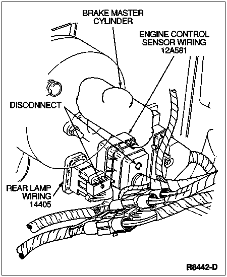
Disconnect connectors from rear lamp wiring (14405) and engine control sensor wiring (12A581) to instrument panel (04320) in engine compartment by loosening the bolts and separating the connectors.
Section 01-12: Instrument Panel and Console | 1996 F-150, F-250, F-350, F-Super Duty and Bronco Workshop Manual |
| Description | Tool Number |
|---|---|
| Radio Removing Tool | T87P-19061-A |
Removal
Disconnect battery ground cable (14301).
Disconnect connectors from rear lamp wiring (14405) and engine control sensor wiring (12A581) to instrument panel (04320) in engine compartment by loosening the bolts and separating the connectors.
Remove radio using Radio Removing Tool T87P-19061-A.
Remove right and left side windshield side garnish mouldings (03598).
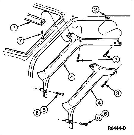
| Item | Part Number | Description |
|---|---|---|
| 1 | 03606 | Windshield Garnish Moulding |
| 2 | 24356 | Body Pillar Trim Panel |
| 3 | N801157-S58 | Screw and Washer (3 Req'd) |
| 4 | 03598 | Windshield Side Garnish Moulding |
| 5 | N806878-S58 | Screw and Washer (RH) |
| 6 | N804992-S424 | Screw and Washer (LH) |
| 7 | N806578-S58 | Screw and Washer (RH) |
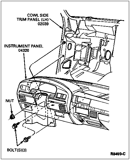
Remove four screws attaching top of instrument panel to cowl top.
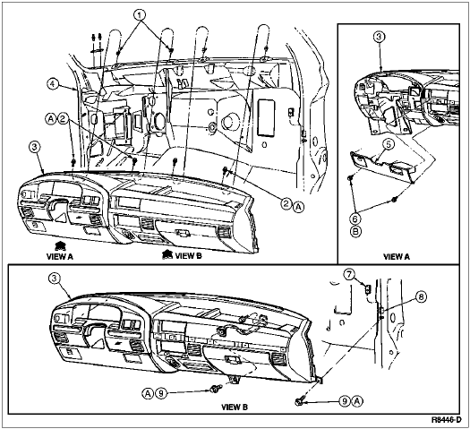
| Item | Part Number | Description |
|---|---|---|
| 1 | N805849-S | Nut Insert (4 Req'd) |
| 2 | N807127-S411 | Screw(s) |
| 3 | 04320 | Instrument Panel |
| 4 | 02039 | Cowl Side Panel (LH) |
| 5 | 044F08 | Steering Column Opening Cover |
| 6 | N803876-S36 | Screw(s) |
| 7 | N800854-S32B | U-Nut |
| 8 | 02038 | Cowl Side Panel (RH) |
| 9 | N606676 | Screw(s) |
| A | Ś | Tighten to 2-2.4 Nm (18-21 Lb-In) |
| B | Ś | Tighten to 2-3 Nm (18-27 Lb-In) |
Remove hood latch control handle and cable (16916) from left cowl side panel (02039) and lay assembly on front floor.
Remove right cowl side panel (02038) and left cowl side panel.
Remove two screws securing the instrument panel steering column opening cover assembly to underside of instrument panel.
Remove cover by pulling at top of cover to unsnap the four retaining clips.
Pull radio antenna lead in cable (18812) down and unsnap wire from bottom of instrument panel and lay wire on floor carpet (13000).
NOTE: Some vehicles may have two lower braces.
Remove bolt attaching instrument panel to panel brace.
Remove screw and washer assembly located at lower corner on right side of instrument panel.
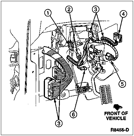
Disconnect the wiring connectors from the main wiring (14401) harness at right cowl side panel.
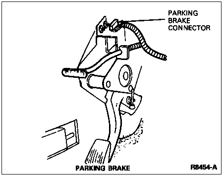
Disconnect the wiring connector from the parking brake control (2780).
Remove three nuts attaching the parking brake control to the left cowl side panel and lay assembly on floor carpet. Do not disconnect the parking brake cable.
Vehicles with column shift: disconnect the shift cable from the steering column and shift cable and bracket (7E395).
Disconnect the wiring connector from the brake light switch.
Vehicles with manual transmission: disconnect the wiring connector from the clutch interlock switch.
| Item | Part Number | Description |
|---|---|---|
| 1 | 13480 | Stoplamp Switch |
| 2 | Ś | To Stoplamp Switch (Part of 14401) |
| 3 | 14401 | Main Wiring |
| 4 | Ś | To Clutch Interlock Switch (Part of 14401) |
| 5 | Ś | To Pedal Position Sensor, D.I. Turbo (Part of 14401) |
| 6 | Ś | To Idle Position Sensor, D.I. Turbo (Part of 14401) |
Disconnect the wiring connectors from main wiring at left cowl side panel.
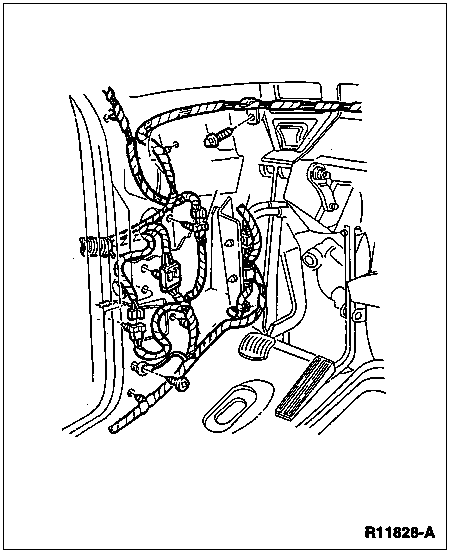
Remove pinch bolt from steering column to lower steering column shaft (3B676). Compress lower steering column shaft toward engine and separate from the column U-joint.
NOTE: Steps 21, 22 and 23 require two technicians.
Support the instrument panel and remove the three bolts and one nut attaching the left side of instrument panel.
Pull instrument panel rearward and disconnect the heater controls (18549) and air conditioner vacuum line connector, if equipped. Disconnect any remaining wiring harnesses.
Carefully remove instrument panel from vehicle through front door (20124).
If replacing instrument panel, transfer all components to the replacement instrument panel.
Installation
NOTE: When the battery (10655) is disconnected and reconnected, some abnormal drive symptoms may occur while the powertrain control module (PCM) (12A650) relearns its adaptive strategy. The vehicle may need to be driven 16 km (10 miles) or more to relearn the strategy.
Follow removal procedures in reverse order.

| Item | Part Number | Description |
|---|---|---|
| 1 | 19E630 | A/C Side Window Demister and Hose (RH) |
| 2 | 19B632 | A/C Accumulator Tube Support Clip |
| 3 | 19E630 | A/C Side Window Demister and Hose (LH) |
| 4 | 19893 | A/C Registers |
| 5 | 061A40 | Glove Compartment Door Latch Cover |
| 6 | 06024 | Glove Compartment |
| 7 | 06115 | Glove Compartment Bumpers |
| 8 | 106004 | Glove Compartment Door Latch |
| 9 | N805979-S | Glove Compartment Bumpers |
| 10 | 5A563 | Lamp and Catch Assembly |
| 11 | 04282 | Pad and Retainer |
| 12 | 19N236 | Power Point |
| 13 | 01657 | Steering Column Opening Insulator |
| 14 | 04320 | Instrument Panel |
| 15 | 19E726 | Duct and Support Assembly |
| 16 | 18C367 | Defrost Seal Nozzle |
| 17 | 19E680 | Connector |
| 18 | 19C901 | Demister Seal |
| 19 | 19C901 | A/C Seal |
| 20 | 047A32 | Instrument Panel Center Bracket |
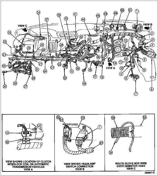
| Item | Part Number | Description |
|---|---|---|
| 1 | Ś | Wiring to Headlamp Switch (Part of 14401) |
| 2 | Ś | Wiring to Fuse Box (Part of 14401) |
| 3 | 14A282-CB | Retainer |
| 4 | N606678-S36 | Screw |
| 5 | 12A581 | Engine Control Sensor Wiring |
| 6 | Ś | Connector to 14A504 (Part of 14401) |
| 7 | 13K359 | Multi-Function Switch |
| 8 | Ś | Connector to Stoplamp Switch (Part of 14401) |
| 9 | Ś | Clip |
| 10 | Ś | E4OD Pigtail (Part of 14401) |
| 11 | Ś | Connector to Park Lamp Signal Switch (Part of 14401) |
| 12 | 14405 | Rear Lamp Wiring |
| 13 | Ś | Wiring to Ignition Switch and Steering Column (Part of 14401) |
| 14 | Ś | Connector to Clutch Interlock Switch (Part of 14401) |
| 15 | Ś | Wiring to Remote Keyless Entry Module |
| 16 | Ś | Connector to Warning Buzzer Chime (Part of 14401) |
| 17 | Ś | Connector to Remote Keyless Entry Module |
| 18 | Ś | Air Bag Module |
| 19 | Ś | Connector to Overspeed Warning (Part of 14401) |
| 20 | Ś | Connector to Trailer Brake Connector (Part of 14401) |
| 21 | 14A099 | Wiring Shield (2 Req'd) |
| 22 | Ś | Vacuum Hose Clip |
| 23 | Ś | Connector to Ash Receptacle Wiring (Part of 14401) |
| 24 | Ś | Connector to PSOM Test Circuit (Part of 14401) |
| 25 | 14A265 | Connector to 14A265 Wiring Assembly |
| 26 | 14B095 | Connector to 14B095 Wiring Assembly |
| 27 | 18A586 | Connector to 18A586 Wiring Assembly |
| 28 | Ś | Connector to Right Courtesy Lamp Switch (Part of 14401) |
| 29 | Ś | Connector to Inertia Switch (Part of 14401) |
| 30 | Ś | Wiring to Ground (Part of 14401) |
| 31 | Ś | Connector to Clearance Lamp (Part of 14401) |
| 32 | Ś | Connector to Wiper Control Module (Part of 14401) |
| 33 | Ś | Wiring to Rear Brake Anti-Lock Control Module (Part of 14401) |
| 34 | Ś | Wiring to Glovebox Lamp (Part of 14401) |
| 35 | Ś | Wiring to Brake Anti-Lock Module Test Circuit (Part of 14401) |
| 36 | Ś | Wiring to Radio Antenna (Part of 14401) |
| 37 | Ś | Wiring to Bowden Cable (Part fo 14401) |
| 38 | Ś | Wiring to Cigar Lighter (Part of 14401) |
| 39 | Ś | Wiring to Heater Mode Switch (Part of 14401) |
| 40 | Ś | Wiring to A/C Illumination (Part of 14401) |
| 41 | Ś | Connector to Radio (Part of 14401) |
| 42 | Ś | Wiring to A/C Blower Switch (Part of 14401) |
| 43 | Ś | Wiring to Power Point (Part of 14401) |
| 44 | Ś | Connector to Premium Sound Amplifier (Part of 14401) |
| 45 | Ś | Wiring to Shift on the Fly Switch (SOF) (Part of 14401) |
| 46 | 14A262 | Wiring to Electric Defroster (Bronco) |
| 47 | 14401 | Main Wiring |
| 48 | Ś | Take-Out to SOF Switch, and Electric Defrost Switch (Part of 14401) |
| 49 | Ś | Wiring to Cluster (Plug A) (Part of 14401) |
| 50 | Ś | Wiring to PSOM (Part of 14401) |
| 51 | Ś | Wiring to Cluster (Plug B) (Part of 14401) |
| 52 | 14B155-BA | Cap |
| 53 | 04320 | Instrument Panel |
| 54 | Ś | Connector to Dual Fuel Tank Switch (Part of 14401) |
| 55 | Ś | Connector to Rear Window Control Switch (Bronco) (Part of 14401) |
| 56 | Ś | Demister Hose (Part of 04320) |
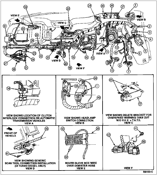
| Item | Part Number | Description |
|---|---|---|
| 1 | Ś | Wiring to Headlamp Switch (Part of 14401) |
| 2 | Ś | Wiring to Fuse Box (Part of 14401) |
| 3 | 14A262 | Wiring Harness Retainer |
| 4 | N606678-S36 | Screw |
| 5 | 12A581 | Engine Control Sensor Wiring (Part of 14401) |
| 6 | Ś | Connector to 14A504 Wiring Assembly (Part of 14401) |
| 7 | 13K359 | Multi-Function Switch |
| 8 | Ś | Wiring to Stoplamp Switch (Part of 14401) |
| 9 | Ś | E40D Pigtail (Part of 14401) |
| 10 | Ś | Connector to Park Signal Lamp Switch (Part of 14401) |
| 11 | 14405 | Rear Lamp Wiring |
| 12 | Ś | Connector to Ignition Switch (Part of 14401) |
| 13 | Ś | Connector to Accelerator Pedal Assembly (Diesel Only) (Part of 14401) |
| 14 | Ś | Connector to Clutch Interlock Switch (Part of 14401) |
| 15 | Ś | Connector to Remote Keyless Entry Programmer (Part of 14401) |
| 16 | Ś | Remote Keyless Entry Module |
| 17 | 14A163-B | Retainer Assembly |
| 18 | Ś | Connector to Warning Buzzer Chime (Part of 14401) |
| 19 | Ś | Connector to Trailer Brake Controller (Part of 14401) |
| 20 | Ś | Vacuum Connector (Part of 14401) |
| 21 | Ś | Connector to Ash Receptacle Wiring (Part of 14401) |
| 22 | Ś | Connector to PSOM Circuit (Part of 14401) |
| 23 | Ś | Connector to Clearance Lamp |
| 24 | 14A265 | Connector to 14A265 Wiring Assembly |
| 25 | 18A856 | Connector to 18A856 Wiring Assembly |
| 26 | Ś | Wiring to Ground (Part of 14401) |
| 27 | Ś | Connector to Right Courtesy Lamp Switch (Part of 14401) |
| 28 | Ś | Wiring to Anti-Lock Brake Module Test Circuit (Part of 14401) |
| 29 | Ś | Radio Antenna |
| 30 | Ś | To Rear Anti-Lock Brake Control Module |
| 31 | 17D539-AA | Wiper Control Module |
| 32 | Ś | Wiring to Glovebox Lamp (Part of 14401) |
| 33 | Ś | Connector to Radio (Part of 14401) |
| 34 | Ś | Wiring to 3x3 Warning Module (Part of 14401) |
| 35 | Ś | Wiring to Cluster (Part of 14401) |
| 36 | Ś | Wiring to PSOM (Part of 14401) |
| 37 | Ś | Wiring to Cluster (Part of 14401) |
| 38 | Ś | Connector to Dual Fuel Tanks Switch (Part of 14401) |
| 39 | 04320 | Instrument Panel |
| 40 | 14401 | Main Wiring |
| 41 | N803876-S36B | Screw |
| 42 | Ś | Demister Hose |
| 43 | Ś | Wiring to ERBP Test Connector (Part of 14401) |