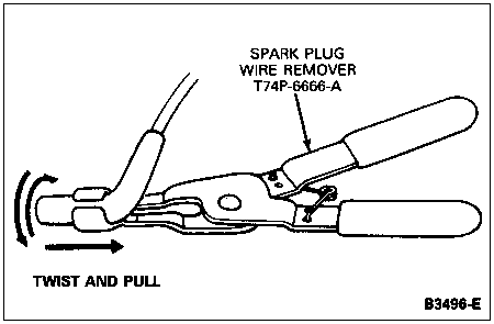
Disconnect distributor to spark plug wires (12286) at the spark plugs (12405) using Spark Plug Wire Remover T74P-6666-A and move out of the way. Disconnect and remove the distributor cap (12106) and distributor to spark plug wires as an assembly.
Section 03-01C: Engine, 7.5L MFI | 1996 F-250, F-350, F-Super Duty Chassis Cab and Motorhome Workshop Manual |
| Description | Tool Number |
|---|---|
| Spark Plug Wire Remover | T74P-6666-A |
Removal
NOTE: On F-250 and F-350 vehicles, it is possible to remove upper intake manifold (9424) and lower intake manifold as an assembly.
Remove air cleaner outlet tube (9B659) and engine air cleaner (ACL) (9600).
Disconnect battery ground cable (14301).
Position a drain pan and drain radiator (8005).
Remove secondary air injection system from right side of engine (6007).
Remove ignition coil mounting strap (12043) from engine and remove high-tension lead at the ignition coil (12029).
Disconnect and remove EGR valve to exhaust manifold tube (9D477).
Disconnect upper radiator hose (8260) at engine.
Disconnect heater hoses at lower intake manifold and water pump (8501). Loosen water bypass tube (8548) at lower intake manifold.
Disconnect positive crankcase ventilation valve (PCV valve) (6A666). Disconnect all the vacuum lines at rear of lower intake manifold and tag them for reference during installation.
Disconnect distributor to spark plug wires (12286) at the spark plugs (12405) using Spark Plug Wire Remover T74P-6666-A and move out of the way. Disconnect and remove the distributor cap (12106) and distributor to spark plug wires as an assembly.
Remove distributor (12127). Refer to Section 03-07A.
Disconnect accelerator linkage and transmission kickdown linkage at the throttle body (9E926). Remove speed control linkage bracket, if so equipped, from the upper intake manifold and disconnect it from the throttle body. Remove bolts holding accelerator linkage cable, and position linkage out of way.
Perform all fuel charging system pre-service procedures. Refer to Section 03-04C. Using Spring Lock Coupling Disconnect Tool D87L-9280-A or -B or equivalent, disconnect fuel lines at fuel injection supply manifold (9F792).
Disconnect engine wiring harness from main wiring harness engine. Remove engine wiring harness and lower intake manifold as an assembly.
Disconnect engine vacuum harness from vacuum reservoir at right-hand fender apron.
Remove attaching bolts. Remove lower intake manifold using engine lifting eyes (17A084). If necessary to pry lower intake manifold away from the cylinder heads (6049), do not damage the gasket sealing surfaces.
Remove and discard intake manifold gaskets and front and rear intake manifold-to-cylinder block seals.
Transfer components as required.
Remove all gasket material from the machined surfaces of the lower intake manifold. Clean the lower intake manifold in a suitable solvent and dry it with compressed air.
Inspect the lower intake manifold for cracks, damaged gasket surfaces, or other wear or damage that would make it unfit for further service. Replace all fasteners that are stripped or otherwise damaged. Remove all filings and foreign matter that may have entered the lower intake manifold as a result of repairs.
Installation
Clean mating surfaces of lower intake manifold, cylinder heads, and cylinder block (6010). Use a solvent such as Metal Surface Cleaner F4AZ-19A536-RA or equivalent meeting Ford specification WSE-M5B392-A.
Apply a 3.175mm (1/8-inch) diameter bead of Gasket Maker E2AZ-19562-B or equivalent meeting Ford specification WSK-M2G348-A5 in and along the joint, the full width of the cylinder block seal mounting surface (four corners) as shown in the following illustration.
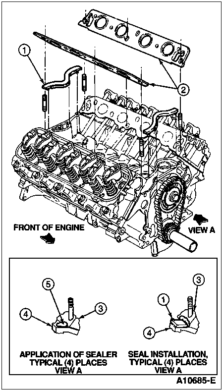
| Item | Part Number | Description |
|---|---|---|
| 1 | � | Seal, Intake Manifold-to-Cylinder Block (Part of 9433) |
| 2 | � | Intake Manifold Gasket (Part of 9433) |
| 3 | 6049 | Cylinder Head |
| 4 | 6010 | Cylinder Block |
| 5 | E2AZ-19562-B | Gasket Maker (4 Places) |
Install the front and rear intake manifold-to-cylinder block seals. Press front and rear intake manifold-to-cylinder block seals firmly into place, distributing sealer into junction of cylinder block and cylinder head as shown.
Install intake manifold gasket.
NOTE: When lower intake manifold is in place, run finger around seal area to make sure front and rear intake manifold-to-cylinder block seals are in place. If front and rear intake manifold-to-cylinder block seals have shifted, remove lower intake manifold and reposition front and rear intake manifold-to-cylinder block seals.
Carefully place lower intake manifold into position over four studs in ends of cylinder heads.
Make sure intake manifold gaskets are properly aligned. Then, install attaching bolts and stud bolts into holes 1 through 10.
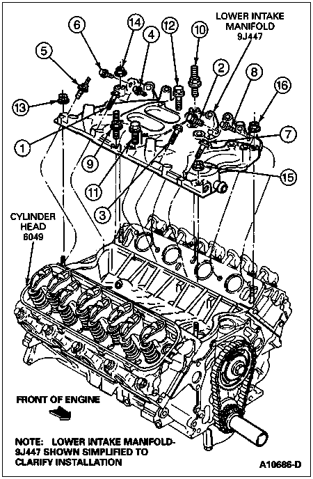
Install bolts into holes 11 and 12.
The lower intake manifold fasteners are secured following a three-step rundown procedure.
Install EGR valve to exhaust manifold tube and secondary air injection system.
Install water bypass tube to lower intake manifold.
Connect upper radiator hose to engine.
Rotate crankshaft vibration damper (6316) until No. 1 piston is at TDC at end of compression stroke. Install the distributor. Refer to Section 03-07A.
Connect heater hoses at lower intake manifold and water pump.
Connect positive crankcase ventilation valve.
Connect fuel lines to fuel injection supply manifold.
Install ignition coil mounting straps.
Complete all electrical connections.
Position accelerator linkage on upper intake manifold. Attach accelerator linkage cable. Attach speed control linkage bracket to upper intake manifold, if so equipped. Install accelerator and kickdown linkage to throttle body.
Connect the vacuum lines to their respective ports at rear of lower intake manifold.
Secure distributor cap to distributor. Connect distributor to spark plug wires to spark plugs. Connect high tension lead to ignition coil.
Fill and bleed the cooling system. Refer to Section 03-03.
NOTE: When the battery (10655) has been disconnected and reconnected, some abnormal drive symptoms may occur while the powertrain control module (PCM) (12A650) relearns its adaptive strategy. The vehicle may need to be driven 16 km (10 miles) or more to relearn the strategy.
Connect the battery ground cable.
Perform all fuel charging system post-service procedures. Refer to Section 03-04C.
Start engine. Check and adjust ignition timing, if necessary.
Operate engine at fast idle and check for coolant leaks. Check coolant level and refill as necessary.
Start the engine and allow it to reach normal operating temperature. Then, while hot, tighten the lower intake manifold attaching nuts and bolts to 30-47 Nm (22-35 lb-ft).
Install engine air cleaner and air cleaner outlet tube assembly.