Section 06-00: Brake System, Service
1996 F-150, F-250, F-350, F-Super Duty Chassis Cab, Motorhome Chassis and Bronco Workshop Manual
ADJUSTMENTS

Brake Load Sensor Proportioning Valve, F-Super Duty Vehicles (Except Motorhome Chassis)

Inspect the vehicle to determine if the rear suspension has been modified. If the rear suspension has been modified, the ride height and spring rate have been altered and the brake load sensor proportioning valve cannot work properly. However, if the suspension has not been modified the brake load sensor proportioning valve may be reset and linkage may be replaced as follows:

SPECIAL SERVICE TOOL(S) REQUIRED
DescriptionTool Number
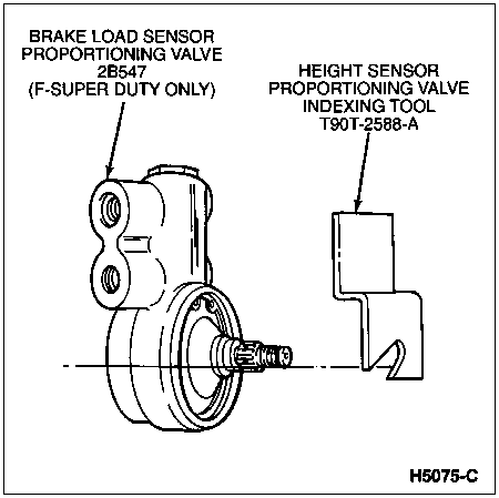
Height Sensor Proportioning Valve Indexing ToolT90T-2588-A

  1. NOTE: Refer to Section 06-06 for brake load sensor proportioning valve removal and installation procedures.

    Raise the rear of the vehicle with body jacks to attain a clearance of 168mm (6.6 inch) between the bottom surface of each rear axle bumper (4730) and the rear axle (4001).


    Brake Load Sensor Proportioning Valve, F-Super Duty (Except Motorhome Chassis)
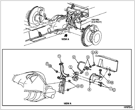


    ItemPart NumberDescription
    12B547Brake Load Sensor Proportioning Valve
    22265Brake Tube
    3388949-SCopper Washer
    42282Rear Brake Hose
    5385116-S2Bolt
    6N605789Bolt
    756522Bolt
    82B256Bracket
    9379930Nut
    10379930Nut
    112C193Linkage
    A—Tighten to 23-34 Nm
    (17-25 Lb-Ft)
    B—Tighten to 26-41 Nm
    (19-30 Lb-Ft)
    C—Tighten to 29.7-40.3 Nm
    (22-29 Lb-Ft)
    D—Tighten to 34-46 Nm
    (26-33 Lb-Ft)
    E—Tighten to 14.8-20.2 Nm (11-14 Lb-Ft)
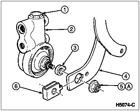
  1. Remove the nut from the valve shaft and remove the leading arm of the linkage assembly. Save the nut.


    ItemPart NumberDescription
    1—Hex-Head Plug
    (Part of 2B547)
    22B547Brake Load Sensor Proportioning Valve
    3—Bushing (Part of 2B547)
    42C193Linkage Assembly
    5379930-S2Nut
    6—Clip (Part of 2C193)
    A—Tighten to 14.8-20.2 Nm (11-14 Lb-Ft)
  1. Remove the bushing and clip from the leading arm of the linkage assembly.

  1. Install the new bushing and clip provided in the linkage kit E8TZ-2L193-A or equivalent.

  1. Rotate the valve shaft one full turn in either direction. Position the shaft with the flat at the bottom and parallel with the ground.


  1. Install the Height Sensor Proportioning Valve Indexing Tool T90T-2588-A on the shaft so the flat on the tool aligns with the flat on the valve shaft. Make sure the valve shaft is nested fully in the tool opening and the upper surface of the tool rests on the valve body.

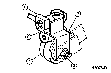
  1. Make sure the tool and valve shaft are firmly engaged. Rotate the indexing tool counterclockwise until the edge surface of the tool contacts the brake hose block.


    ItemPart NumberDescription
    12282Rear Brake Hose
    2T90T-2588-AHeight Sensor Proportioning Valve In dexing Tool
    3—Brake Load Sensor Proportioning Valve Shaft Seated in Tool Slot
    42B547Brake Load Sensor Proportioning Valve
    5—Indexing Tool Seated Against Rear Brake Hose Block
  1. While holding the indexing tool in the position established in Step 6, install the leading arm of the linkage assembly over the splined section of the valve shaft. Use a 1/2-inch deep socket as a driver and tap it with a hammer to fully seat the linkage on the splines.

  1. Reinstall the valve shaft nut removed in Step 2. Tighten the nut to 14.8-20.2 Nm (11-14 lb-ft).

  1. Remove the indexing tool.