Section 06-07A: Brake, Power, Vacuum, Single and Tandem Diaphragm | 1996 F-150, F-250, F-350, and Bronco Workshop Manual |
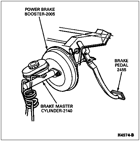
This section provides service information for the power brake boosters (2005) (single and tandem) using engine manifold vacuum. Information for the vacuum pump brake system is given in Section 06-07B and for the hydro-boost system in Section 06-07C.
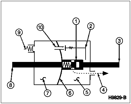
A vacuum-type power brake booster is a container whose inner space is divided by a diaphragm into two separate chambers, A and B. The brake pedal-to-power brake booster push rod enters on one side, and the brake master cylinder push rod exits on the other. The diaphragm is shown by the curved line in the center. Notice that the brake master cylinder push rod is attached to the center of the diaphragm.
There are three valves that control the vacuum in the power brake booster. The power brake booster check valve opens to allow the intake manifold vacuum to evacuate the power brake booster. When it closes, it holds the vacuum in the chambers.
The equalizer valve links the two chambers. When it is open, the vacuum in the chambers can equalize. When it closes, the chambers are separated.
The vacuum bleed valve functions to reduce the amount of vacuum in
chamber B when boost is required.

| Item | Part Number | Description |
|---|---|---|
| 1 | — | Vacuum Bleed Valve (Part of 2005), Closed |
| 2 | — | Equalizer Valve Linkage (Part of 2005) |
| 3 | — | Brake Pedal-to-Power Brake Booster Push Rod (Part of 2005) |
| 4 | — | Vent to Atmosphere (Part of 2005) |
| 5 | — | Vacuum Chamber B (Part of 2005) |
| 6 | — | Diaphragm (Part of 2005) |
| 7 | — | Vacuum Chamber A (Part of 2005) |
| 8 | — | Power Brake Booster-to-Brake Master Cylinder Push Rod (Part of 2005) |
| 9 | 2365 | Power Brake Booster Check Valve |
| 10 | — | Equalizer Valve (Part of 2005), Open |
As the brake pedal-to-power brake booster push rod moves forward, its motion closes the equalizer valve. This isolates chambers A and B, but they are still under vacuum.
As the brake pedal-to-power brake booster push rod moves ahead further, a port in the brake pedal-to-power brake booster push rod begins to line up with ports in the sleeve. This vents chamber B to the outside and reduces the amount of vacuum in chamber B.
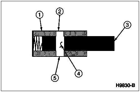
| Item | Part Number | Description |
|---|---|---|
| 1 | — | Sleeve (Part of 2005) |
| 2 | — | Sleeve Port (Part of 2005), Open |
| 3 | — | Brake Pedal-to-Power Brake Booster Push Rod (Part of 2005) |
| 4 | — | Brake Pedal Push Rod Port (Part of 2005), Open |
| 5 | — | Sleeve Port (Part of 2005), Open |
With more vacuum in chamber A and less in chamber B, the diaphragm is forced forward in the direction of the brake master cylinder (2140). This force acts on the brake master cylinder push rod, providing a boost.
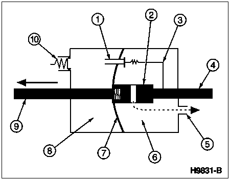
| Item | Part Number | Description |
|---|---|---|
| 1 | — | Equalizer Valve (Part of 2005), Closed |
| 2 | — | Vacuum Bleed Valve (Part of 2005), Open |
| 3 | — | Equalizer Valve Linkage (Part of 2005) |
| 4 | — | Brake Pedal-to-Power Brake Booster Push Rod (Part of 2005) |
| 5 | — | Vent to Atmosphere (Part of 2005) |
| 6 | — | Vacuum Chamber B (Part of 2005), Less Vacuum |
| 7 | — | Diaphragm (Part of 2005), Deflected by Pressure Differential |
| 8 | — | Vacuum Chamber A (Part of 2005) |
| 9 | — | Power Brake Booster-to-Brake Master Cylinder Push Rod (Part of 2005) |
| 10 | 2365 | Power Brake Booster Check Valve |
The vacuum bleed valve is not just an open/close valve. A spring is shown at the forward end of the brake pedal-to-power brake booster push rod to indicate an important point.
Depending on how hard the driver pushes on the brake pedal (2455), the brake pedal-to-power brake booster push rod and the sleeve slide back and forth in relation to each other as they move forward. This opens and closes the vent in such a way that only the required amount of vacuum is drawn down.
Braking hard bleeds off more vacuum, producing more boost. Brake lightly, and less boost results. Once the level of boost corresponds to the applied brake pedal force, the vacuum bleed valve closes and holds that level of vacuum.
Step-Through
If enough force is applied to the brake pedal-to-power brake booster push rod, the rod moves forward enough to come in direct contact with the power brake booster-to-brake master cylinder push rod where it connects to the diaphragm. At this point, all available boost has been provided and force is directly applied to the power brake booster-to-brake master cylinder push rod mechanically. This point is called "step-through," and only occurs with low vacuum or excessive power brake booster-to-brake master cylinder pedal force.
Brakes Released
When the driver takes his or her foot off the brake pedal, the brake pedal-to-power brake booster push rod retracts. As it retracts, the equalizer valve opens and equalizes the vacuum in both chambers. This brake pedal-to-power brake booster push rod slides with the sleeve and remains in the closed position. If vacuum is available at the power brake booster check valve, the power brake booster recharges itself, ready for the next application of the brakes.
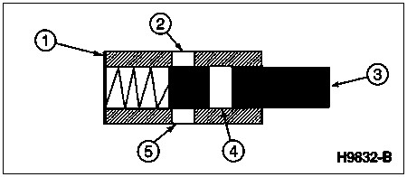
| Item | Part Number | Description |
|---|---|---|
| 1 | — | Sleeve (Part of 2005) |
| 2 | — | Sleeve Port (Part of 2005), Closed |
| 3 | — | Brake Pedal-to-Power Brake Booster Push Rod (Part of 2005) |
| 4 | — | Brake Pedal Push Rod Port (Part of 2005), Closed |
| 5 | — | Sleeve Port (Part of 2005), Closed |
On vehicles with gasoline engines (6007) and vacuum type power brake boosters, the boost will renew itself quickly. When the boost is needed again, it will be fully there. However, if something happens to prevent the vacuum from developing, boost will decrease with each application, until the remaining vacuum is used up.
Tandem Boosters
On some larger vehicles using vacuum-boosted brakes, additional boost force is supplied by tandem type power brake boosters. Tandem type power brake boosters have two sets of vacuum chambers instead of one. This substantially increases the diaphragm surface area, which in turn increases the boost. Otherwise, tandem type power brake boosters work the same as a single chamber type power brake booster.
For the same brake pedal force, more hydraulic line pressure is created with a tandem type power brake booster. This results in longer brake pedal travel, causing the brakes to feel springier. This is normal. Springy should not be confused with spongy.
On diesel applications, tandem vacuum brakes may experience greater brake pedal drop than single type power brake boosters as the vacuum pump (2A451) rebuilds vacuum in the chamber following brake applications. This is a normal characteristic.
A vacuum pump provides power to the power brake booster on diesel engines, which have no manifold vacuum. Refer to Section 06-07B for vacuum pump service procedures.
Vacuum Boosters, Diesel Powered Vehicles
Diesel powered vehicles require a pump to develop the vacuum for the booster, since there is no intake manifold vacuum. The capacity of these pumps is small compared to the displacement of a gasoline engine. As a result, a diesel vacuum pump takes longer to recover after brake application. Repeated applications of the brakes may limit the boost and change the feel of the brake pedal.
For example, after braking to a hard stop, the vacuum in a diesel booster may be significantly reduced. If the driver continues to apply the brakes at the stop, the vacuum will start to build again and the pedal will sink as the increasing boost moves the diaphragm forward. This doesn't mean there is a fluid leak or a malfunction in the system. Always check the vacuum supply on a diesel before suspecting other defects when the complaint is pedal drop.