Section 06-07A: Brake, Power, Vacuum, Single and Tandem Diaphragm | 1996 F-150, F-250, F-350, and Bronco Workshop Manual |
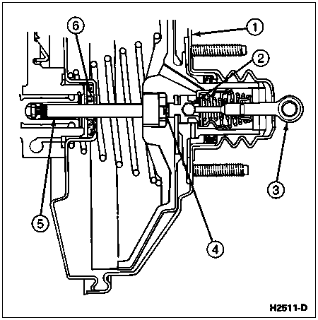
![]() CAUTION: Make sure the power brake booster rubber reaction disc is properly installed as shown in the illustration. If the power brake booster-to-brake master cylinder push rod is removed or accidentally pulled out, it may dislodge the power brake booster rubber reaction disc from its seat in the power brake booster (2005). Symptoms of a dislodged power brake booster rubber reaction disc are excessive brake pedal travel and extreme power brake sensitivity. If the power brake booster-to-brake master cylinder push rod is removed, remove the power brake booster front seal and look into the power brake booster to where the power brake booster-to-brake master cylinder push rod seats. The power brake booster rubber reaction disc is black rubber. If the power brake booster rubber reaction disc is dislodged, a silver colored valve plunger will be exposed.
If the power brake booster rubber reaction disc cannot be located, installed and aligned, then the power brake booster unit must be replaced.
CAUTION: Make sure the power brake booster rubber reaction disc is properly installed as shown in the illustration. If the power brake booster-to-brake master cylinder push rod is removed or accidentally pulled out, it may dislodge the power brake booster rubber reaction disc from its seat in the power brake booster (2005). Symptoms of a dislodged power brake booster rubber reaction disc are excessive brake pedal travel and extreme power brake sensitivity. If the power brake booster-to-brake master cylinder push rod is removed, remove the power brake booster front seal and look into the power brake booster to where the power brake booster-to-brake master cylinder push rod seats. The power brake booster rubber reaction disc is black rubber. If the power brake booster rubber reaction disc is dislodged, a silver colored valve plunger will be exposed.
If the power brake booster rubber reaction disc cannot be located, installed and aligned, then the power brake booster unit must be replaced.

| Item | Part Number | Description |
|---|---|---|
| 1 | 2005 | Power Brake Booster |
| 2 | — | Valve Plunger (Part of 2005) |
| 3 | — | Brake Pedal-to-Power Brake Booster Push Rod (Part of 2005) |
| 4 | — | Power Brake Booster Rubber Reaction Disc (in Position) (Part of 2005) |
| 5 | — | Power Brake Booster-to- Brake Master Cylinder Push Rod (Part of 2005) |
| 6 | — | Power Brake Booster Front Seal (Part of 2005) |
Removal
NOTE: When the battery is disconnected and reconnected, some abnormal drive symptoms may occur while the powertrain control module (PCM) (12A650) relearns its adaptive strategy. The vehicle may need to be driven 16 km (10 miles) or more to relearn the strategy.
Disconnect the battery ground cable (14301).
Support the power brake booster from the underside with a prop.
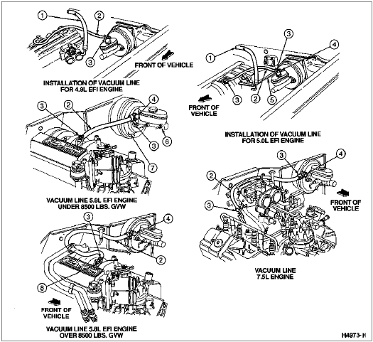
Loosen the clamp that secures the vacuum booster hose to the power brake booster check valve, and remove the vacuum booster hose. Remove the power brake booster check valve.
Remove the wraparound clip (securing brake lines) from power brake booster inboard stud.
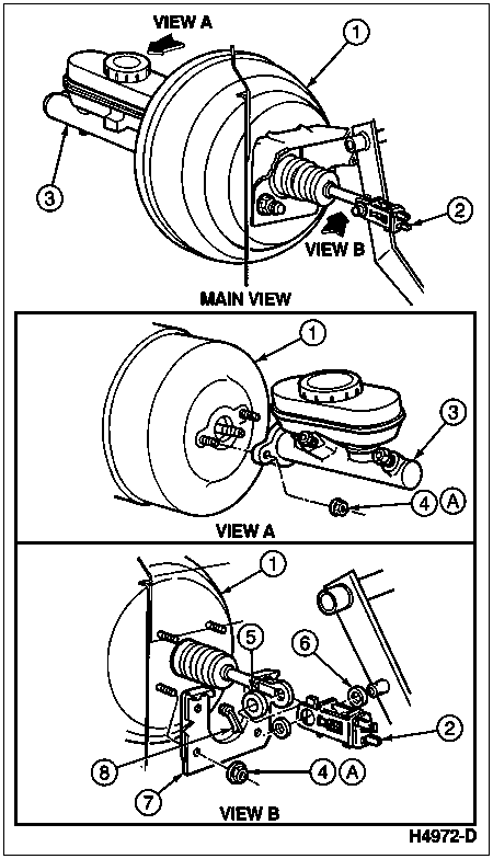
Remove the brake master cylinder-to-power brake booster retaining nuts.
Pull the brake master cylinder (2140) off the power brake booster and leave it supported by the prop, far enough away to allow removal of the power brake booster.
From inside the cab, remove the cotter pin and slide the stoplight switch (13480), brake master cylinder push rod spacers (2B129) and brake master cylinder push rod bushing (2474) off the brake pedal pin.
From inside the cab, remove the nuts retaining the power brake booster to the dash. Remove the power brake booster from the engine compartment.

| Item | Part Number | Description |
|---|---|---|
| 1 | 2005 | Power Brake Booster |
| 2 | 13480 | Stoplight Switch |
| 3 | 2140 | Brake Master Cylinder |
| 4 | 382802-S2 | Nut |
| 5 | 2474 | Brake Master Cylinder Push Rod Bushing |
| 6 | 2B129 | Brake Master Cylinder Push Rod Spacer |
| 7 | 2467 | Brake Pedal Bracket |
| 8 | 380699-S100 | Self-Locking Pin |
| A | — | Tighten to 20-28 Nm (15-21 Lb-Ft) |
Installation
NOTE: Make sure the brake pedal-to-power brake booster push rod is positioned on the correct side of the brake pedal (2455) to install onto the brake pedal pin prior to tightening the power brake booster to the dash.
Mount the power brake booster on the engine side of the dash panel by sliding the brake pedal bracket mounting studs and brake pedal-to-power brake booster push rod in through the holes in the dash.
Install the brake pedal bracket-to-dash panel retaining nuts from inside the cab. Tighten nuts to 20-28 Nm (15-21 lb-ft).
Position the brake master cylinder on the power brake booster. Install the retaining nuts and remove the prop from underneath the brake master cylinder. Tighten nuts to 20-28 Nm (15-21 lb-ft).
Install the wraparound clip on the booster inboard stud.
Install the power brake booster check valve. Connect the vacuum booster hose to the power brake booster check valve and secure with the clamp. Make sure the vacuum booster hose is routed as shown.
Install the brake master cylinder push rod spacers and position the stoplight switch on the end of the brake pedal-to-power brake booster push rod from inside the cab. Then install the stoplight switch and brake pedal-to-power brake booster push rod on the brake pedal pin, along with brake master cylinder push rod bushings on each side, and secure with the self-locking pin.
Connect the stoplamp switch wiring.
Reconnect battery ground cable.
Start the engine (6007) and check brake operation.

| Item | Part Number | Description |
|---|---|---|
| 1 | 19867 | Air Conditioning Hose |
| 2 | 381298 | Vacuum Hose |
| 3 | 382984 | Clamp |
| 4 | 2365 | Power Brake Booster Check Valve |
| 5 | 9600 | Engine Air Cleaner |
| 6 | 2140 | Brake Master Cylinder |
| 7 | 2005 | Power Brake Booster |
| 8 | 9A474 | Intake Manifold Vacuum Outlet Fitting and Cap |