Fluid Pressure Flow
Section 06-07C: Brake, Power, Hydro-Boost Booster | 1996 F-Super Duty Chassis Cab and Motorhome Chassis Workshop Manual |
The Bendix Hydro-Boost brake booster is hydraulically operated by the power steering pump (3A674). The power steering pump provides fluid pressure to operate both the power brake booster (2005) and the power steering gear (3504).
A Hydro-Boost reserve system (accumulator) stores sufficient fluid under pressure to provide at least two power-assisted brake applications in the event the power steering pump fluid flow is interrupted.
The brakes can also be applied manually if the reserve system is depleted.
Model identification is stamped into the power brake booster housing near the power steering right turn pressure hose (3A717).
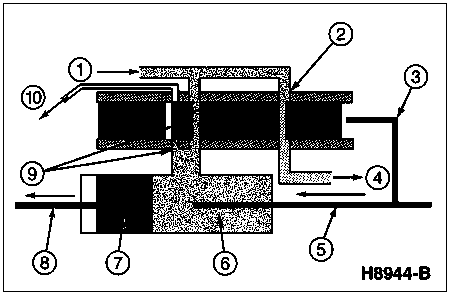
With the Hydro-Boost at rest (engine (6007) on, brakes released), power steering fluid flows from the inlet port, across the land 3 and through the outlet port to the steering gear. In this position, steering pressure created by the steering gear and power steering pump is isolated from the boost cavity by the spool valve. Lands 2 and 4 block this steering pressure which prevents activation of the unit.
Any leakage goes directly back to the power steering oil reservoir (3A697).
Fluid Pressure Flow
| Item | Part Number | Description |
|---|---|---|
| 1 | Ś | Fluid Under Pressure from Power Steering Pump |
| 2 | Ś | Brake Booster Valvebr (Part of 2B560) |
| 3 | Ś | Ratio Lever (Part of 2B560) |
| 4 | Ś | Fluid Under Pressure to Power Steering Gear |
| 5 | Ś | Brake Pedal Push Rodbr (Part of 2B560) |
| 6 | Ś | Booster Cylinder (Part of 2B560) |
| 7 | Ś | Booster Piston (Part of 2B560) |
| 8 | Ś | Master Cylinder Push Rod (Part of 2B560) |
| 9 | Ś | Bleed Valve (Part of 2B560) |
| 10 | Ś | Outlet Port (Part of 2B560) to Power Steering Pump Reservoir |
| Item | Part Number | Description |
|---|---|---|
| 1 | Ś | Outlet Port (Part of 2005) to Power Steering Oil Reservoir |
| 2 | Ś | Inlet Port from Power Steering Pump (Part of 2005) |
| 3 | Ś | Outlet Port to Steering Gear (Part of 2005) |
| 4 | Ś | Accumulator Valve (Part of 2005) |
| 5 | Ś | Secondary Valve (Part of 2005) |
| 6 | Ś | Ratio Lever (Part of 2005) |
| 7 | Ś | Brake Pedal Push Rod (Part of 2005) |
| 8 | Ś | Housing Cover (Part of 2005) |
| 9 | Ś | Power Piston (Part of 2005) |
| 10 | Ś | Accumulator Piston (Part of 2005) |
| 11 | Ś | Accumulator Cap (Part of 2005) |
| 12 | Ś | Nitrogen Gas |
| 13 | Ś | Brake Master Cylinder Push Rod (Part of 2005) |
| 14 | 2005 | Power Brake Booster |
| 15 | Ś | Primary Valve (Part of 2005) |
| 16 | Ś | Spool (Part of 2005) |
| 17 | Ś | Boost Cavity (Part of 2005) |
| 18 | Ś | Land 1 |
| 19 | Ś | Land 2 |
| 20 | Ś | Land 3 |
| 21 | Ś | Land 4 |
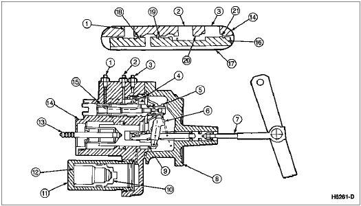
During normal power operation, the brake pedal (2455) is applied as shown in the following illustration by brake pedal push rod travel A. The movement of the ratio lever operates the spool valve, creating hydraulic pressure due to the restriction at land 3. Fluid traverses land 2 and flows through the center of the spool valve into the boost cavity. This pressure acts on the power piston to generate the power assist and against the reaction rod to provide power assist in relation to the effort level applied to the brake pedal.
If, while braking, fluid pressure is required for steering, power steering pump pressure will rise and the spool valve will shift in an open direction, allowing more fluid to flow to the steering gear. Even under extremes of braking, the fluid flow to the steering gear is fully sufficient for steering the vehicle.
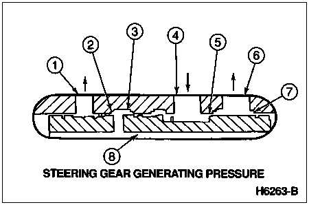
The enlarged view of the spool valve shows the relationship of the valve lands during normal power operation. Land 1 is closed, blocking the oil flow to the power steering oil reservoir. Land 3 meters the flow of oil from the power steering pump to the steering gear and generates the hydraulic pressure that is metered across land 2 to provide assist to the brakes.
Hydro-Boost Booster and Spool Valve, Booster Generating Pressure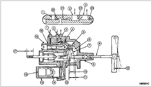
| Item | Part Number | Description |
|---|---|---|
| 1 | Ś | Outlet Port (Part of 2005) to Power Steering Oil Reservoir |
| 2 | Ś | Inlet Port (Part of 2005) to Power Steering Pump (Part of 2005) |
| 3 | Ś | Outlet Port (Part of 2005) to Steering Gear (Part of 2005) |
| 4 | Ś | Accumulator Valve (Part of 2005) |
| 5 | Ś | Secondary Valve (Part of 2005) |
| 6 | Ś | Boost Cavity (Part of 2005) |
| 7 | Ś | Ratio Lever (Part of 2005) |
| 8 | Ś | Brake Pedal Push Rod (Part of 2005) |
| 9 | Ś | Housing Cover (Part of 2005) |
| 10 | Ś | Travel A |
| 11 | Ś | Travel B |
| 12 | Ś | Brake Pedal Push Rod Travel A (Part of 2005) |
| 13 | Ś | Power Piston (Part of 2005) |
| 14 | Ś | Accumulator Piston (Part of 2005) |
| 15 | Ś | Accumulator Cover (Part of 2005) |
| 16 | Ś | Nitrogen Gas |
| 17 | Ś | Brake Master Cylinder Push Rod Travel B |
| 18 | 2005 | Power Brake Booster |
| 19 | Ś | Primary Valve (Part of 2005) |
| 20 | Ś | Land 1 |
| 21 | Ś | Land 2 |
| 22 | Ś | Land 3 |
| 23 | Ś | Land 4 |
The following illustration shows the same operation, except pressure is generated by the steering gear and is also being used for braking. During this mode of operation, the spool valve travel is slightly less than the first case.
| Item | Part Number | Description |
|---|---|---|
| 1 | Ś | Outlet Port (Part of 2005) to Power Steering Oil Reservoir |
| 2 | Ś | Land 1 (Part of 2005) |
| 3 | Ś | Land 2 (Part of 2005) |
| 4 | Ś | Inlet Port (Part of 2005) from Power Steering Pump |
| 5 | Ś | Land 3 (Part of 2005) |
| 6 | Ś | Outlet Port (Part of 2005) to Steering Gear |
| 7 | Ś | Land 4 (Part of 2005) |
| 8 | Ś | Boost Cavity (Part of 2005) |