Rear Anti-Lock Brake System, F-Series

Instrument Cluster Connector C2

Section 06-09A: Brake System, Anti-Lock, Rear | 1996 F-150, F-250, F-350 Workshop Manual |
A wiring diagram is provided which represents the RABS II electrical system. The diagram provides the wire circuit numbers, color codes, connectors, and connections to principal system components. If, after following a particular test procedure, the result is not as indicated, the problem may be located in the wiring itself. This diagram will assist in diagnosing these problems.
Rear Anti-Lock Brake System, F-Series
Instrument Cluster Connector C2
| Pin Number | Circuit | Circuit Function |
|---|---|---|
| 1 | 875 (BK/LB) | Dedicated Ground — Closed Loop |
| 2 | 658 (PK/LG) | PCM to Check Engine Indicator Lamp |
| 3 | 603 (DG) | Rear ABS Warning Light (Yellow) |
| 4 | 977 (P/W) | Dual Brake Warning Switch to Indicator Lamp |
| 5 | — | Not Used |
| 6 | 29 (Y/W) | Fuel Gauge to Fuel Gauge Sender |
| 7 | 3 (LG/W) | Front Turn Signal Lamp (LH) |
| 8 | 31 (W/R) | Oil Pressure Indicator to Oil Pressure Sending Unit |
| 9 | 875 (BK/LB) | Dedicated Ground — Closed Loop |
| 10 | 39 (R/W) | Temperature Gauge to Temperature Sending Unit |
| 11 | 531 (DG/Y) | Brake Fluid Level Warning Indicator |
| 12 | 608 (BK/Y) | Lamp Driver |
| 13 | 640 (R/Y) | Warning Lamps Feed |
| 14 | — | Not Used |

| Pin Number | Circuit | Circuit Function |
|---|---|---|
| 1 | 601 (LB/PK) | Anti-Lock Electronic Control Module Feed |
| 2 | 512 (T/LG) | Fluid Level Switch to Anti-Lock Electronic Control Module |
| 3 | 519 (LG/BK) | RABS Rear Sensor (Low) to Anti-Lock Electronic Control Module |
| 4 | 530 (LG/Y) | Anti-Lock Electronic Control Module to Chassis Ground |
| 5 | 210 (LB) | 4x4 Input |
| 6 | 535 (LB/R) | Pressure Switch to Anti-Lock Electronic Control Module |
| 7 | 603 (DG) | Rear ABS Warning Light Ground |
| 8 | 664 (Y/LG) | Anti-Lock Electronic Control Module to Dump Solenoid |
| 9 | 601 (LB/PK) | Anti-Lock Electronic Control Module Feed |
| 10 | 523 (R/PK) | RABS Sensor (High) to Anti-Lock Electronic Control Module |
| 11 | 511 (LG) | Stoplight Switch Input |
| 12 | 571 (BK/O) | Keep Alive Memory (KAM) Power |
| 13 | 599 (PK/LG) | Anti-Lock Electronic Control Module to Isolation Solenoid |
| 14 | 664 (Y/LG) | Anti-Lock Electronic Control Module to Dump Solenoid |

| Pin Number | Circuit | Circuit Function |
|---|---|---|
| 1 | 904 (LG/R) | Ignition Switch COIL/ACCY to Generator Regulator IGN Terminal |
| 2 | 932 (GY/W) | Daytime Running Lamp |
| 3 | 57 (BK) | Ground Circuit |
| 4 | 450 (DG/LG) | Seat Belt Warning Indicator Lamp Feed |
| 5 | 29 (Y/W) | Fuel Gauge to Fuel Gauge Sender |
| 6 | 19 (LB/R) | Instrument Panel Lamps Feed |
| 7 | 57 (BK) | Ground Circuit |
| 8 | 2 (W/LB) | Front Turn Signal Lamp (RH) |
| 9 | 648 (W/PK) | Tachometer Sensor Feed |
| 10 | 398 (BK/Y) | Tachometer Ground to Tachometer/Gauge Module |
| 11 | 784 (LB/BK) | Low Range Switch to PCM or Indicator Lamp (4 x 4) |
| 12 | 210 (LB) | Indicator Lamp to Switch (4 x 4) |
| 13 | 640 (R/Y) | Warning Lamps Feed |
| 14 | 16 (R/LG) | Ignition Switch to Ignition Coil BATTERY Terminal |

| Pin Number | Circuit | Circuit Function |
|---|---|---|
| A1 | 297 (BK/LG) | Power (Hot in ACC or RUN) |
| A2 | 687 (GY/Y) | Power (Hot in RUN) |
| A3 | 687 (GY/Y) | Power (Hot in RUN) |
| A4 | 687 (GY/Y) | Power (Hot in RUN) |
| B1 | 37 (Y) | Battery Input |
| B2 | 37 (Y) | Battery Input |
| B3 | 37 (Y) | Battery Input |
| B4 | 37 (Y) | Battery Input |
| B5 | 37 (Y) | Battery Input |
| I1 | 16 (R/LG) | Power (Hot in START or RUN) |
| I2 | — | Not Used |
| P1 | 41 (BK/LB) | Bulb Test (Diesel Only) |
| P2 | 512 (T/LG) | Bulb Test (Ground in START) |
| STA | 32 (R/LB) | Power (Hot in START) |
| GND | 57 (BK) | Ground |

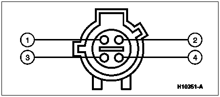
| Pin Number | Circuit | Circuit Function |
|---|---|---|
| 1 | 599 (PK/LG) | Isolation Valve Feed |
| 2 | 664 (Y/LG) | Dump Valve Feed |
| 3 | 274 (BK/W) | Ground |
| 4 | 535 (LB/R) | Valve Reset Switch Feed |