
Section 07-01A: Transmission, Automatic, E4OD | 1996 All F-Series and Bronco with E4OD Automatic Transmission Workshop Manual |
Electronic System Description
The following pages provide a brief description of each of the sensors and actuators used with the E4OD transmission. The function of each of these components and the associated symptoms and diagnostic trouble codes (DTCs) are also given.
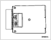
E4OD Automatic Transmission Electronic Control System Component Locator
| On vehicles equipped with gasoline engines, the operation of the E4OD automatic transmission is controlled by the powertrain control module. Many input sensors provide information to the powertrain control module, which then controls the actuators that affect transmission operation. |
| On vehicles equipped with diesel engines, the operation of the E4OD automatic transmission is also controlled by the powertrain control module. However, some of the input sensors are different. |
 |
| Description: The air conditioning clutch is an electromagnetic clutch that is energized when the clutch cycling A/C pressure cut-off switch closes. The A/C pressure cut-off switch is located on the suction accumulator-drier. The closing of the A/C pressure cut-off switch completes the circuit to the clutch and draws it into engagement with the compressor driveshaft. Used as an input to determine electronic pressure control when the air conditioning clutch is engaged to compensate for the additional load on the engine. |
| Symptoms: Failed on Ś electronic pressure control slightly low with A/C off. Failed off Ś electronic pressure control slightly high with A/C on. |
| Diagnostic Trouble Codes: 539, P1460, P1463, P1464. |
 |
| Description: The brake on/off switch tells the powertrain control module when the brakes are applied. The switch is closed when the brakes are applied and open when they are released. The PCM uses this signal to disengage torque converter clutch when brake is applied. |
| Symptoms: Failed on or not connected Ś Torque converter clutch will not engage at less than 1/3 throttle. Failed off Ś Torque converter clutch will not disengage when brake is applied. |
| Diagnostic Trouble Codes: 536, P1703. |
 |
| Description: On gasoline engines, the profile ignition pickup sensor sends a signal to the powertrain control module indicating the engine rpm and the crankshaft position. |
| Symptoms: Engine will stall or miss. |
| Diagnostic Trouble Codes: 211, P0340, P0341, P0344. |
 |
| Description: On the 7.3L DI diesel engines, the CMP sensor provides engine rpm information to the PCM. This rpm input is used to determine shift scheduling and EPC pressure. |
| Symptoms: No start. |
| Diagnostic Trouble Codes: P0340, P0341, P0344 |
 |
| Description: The low range switch is located on the transfer case cover. It provides an indication of when the 4x4 transfer case gear system is in the LOW range. Modifies shift schedule for 4x4L transfer case gear ratio. |
| Symptoms: Failed on Ś Early shift schedule in 4x2 and 4x4H. Failed off Ś Shifts delayed in 4x4L. If the 4x4 low indicator light fuse is blown, the transmission will shift according to 4x4 low shift schedule regardless of transfer case position. |
| Diagnostic Trouble Codes: 633, 691, P1729, P1781. |
 |
| Description: The mass air flow sensor directly measures the mass of air flowing into the engine. The sensor output is a D.C. (analog) signal ranging from 0.5 volt to 5 volts used by the processor to calculate injector pulse width. Used as an input to determine electronic pressure control. |
| Symptoms: High electronic pressure, firm shifts and engagements. |
| Diagnostic Trouble Codes: 157, 158, 159, 184, 185, P0102, P0103, P1100, P1101. |
 |
| Description: On gasoline engines, the manifold absolute pressure (MAP) sensor senses atmospheric pressure to produce an electrical signal. The frequency of this signal varies with intake manifold pressure. The powertrain control module monitors this signal to determine altitude. The PCM then adjusts the E4OD shift schedule and EPC pressure for altitude. |
| On diesel engines, the MAP sensor measures boost pressure. The PCM monitors this signal and adjusts EPC pressure. |
| Symptoms: Firm shift feel, late shifts at altitude. |
| Diagnostic Trouble Codes: 126-129, P0235-P0237. |
 |
| Description: The barometric pressure sensor operates similarly to the manifold absolute pressure sensor. It measures barometric pressure instead of intake manifold pressure. The powertrain control module uses the signal from the barometric pressure sensor to determine the altitude at which the vehicle is operating. The powertrain control module then adjusts the E4OD shift schedule and EPC pressure for the altitude. |
| Symptoms: Firm shift feel, late shifts at altitude. |
| Diagnostic Trouble Codes: P0107, P0108. |
 |
| Description: The programmable speedometer/odometer module receives input from the rear brake anti-lock sensor, which is mounted on the rear axle differential housing. The PSOM processes this input signal information and relays it to the powertrain control module and the speed control module. This signal tells the powertrain control module the vehicle speed in miles per hour (mph). Used as an input in determining shift scheduling and electronic pressure control. |
| Symptoms: Harsh engagements, firm shift feel, abnormal shift schedule, unexpected downshifts may occur at closed throttle, abnormal torque converter clutch operation or engages only at wide-open throttle (WOT). May flash transmission control indicator lamp. |
| Diagnostic Trouble Codes: 452, P0500, P1500, P1501, P0503. |
 |
| Description: The transmission control switch (TCS) is a momentary contact switch. When the switch is pressed, a signal is sent to the powertrain control module. The powertrain control module then energizes the transmission control indicator lamp and the coast clutch solenoid, applying the coast clutch to provide engine braking and cancels fourth gear operation. The TCIL indicates overdrive cancel mode activated (lamp on), electronic pressure control circuit shorted or monitored sensor failure (lamp flashing). |
| Sensor: Transmission Control Switch. |
| Symptoms: No overdrive cancel when switch is cycled. |
| Diagnostic Trouble Codes: 632, P1780, tested during Key On Engine Off (KOEO) On-Board Diagnostic only. |
| Actuator: Transmission Control Indicator Lamp. |
| Symptoms: Failed on Ś overdrive cancel mode always indicated, no flashing for electronic pressure control circuit shorted. Failed off Ś overdrive cancel mode never indicated, no flashing for electronic pressure control circuit shorted, also may be due to a bad fuse. Erratic operation (flashing) may be due to a wiring concern. |
| Diagnostic Trouble Codes: 631, P1779. |
 |
| Description: The throttle position sensor is a potentiometer that is mounted on the throttle body on gas applications and on the fuel injection pump lever on diesel applications. The throttle position sensor detects the position of the throttle plate or lever and sends this information as a voltage signal to the powertrain control module. |
| If a malfunction occurs in the throttle position sensor circuit, the powertrain control module will recognize that the throttle position sensor signal is out of specification. The powertrain control module will then operate the E4OD transmission at a higher line pressure to prevent transmission damage. This high line pressure causes harsh upshift and engagements. Used as an input to determine shift scheduling and electronic pressure control. |
| Symptoms: Harsh engagements, firm shift feel, abnormal shift schedule, abnormal or no torque converter clutch operation. May flash transmission control indicator lamp. |
| Diagnostic Trouble Codes: 121, 122, 123, 124, 125, 167, P0121, P0122, P0123, P1120, P1121, P1124, P1125. |
 |
| Description: The accelerator pedal (AP) sensor is mounted on the accelerator pedal on 7.3L DI diesel engines. The AP sensor detects the position of the accelerator pedal and sends this information as a voltage signal to the PCM. |
| If a malfunction occurs in the AP sensor circuit, the powertrain control module will recognize that the AP sensor signal is out of specification. The powertrain control module will then operate the E4OD transmission at a higher line pressure to prevent transmission damage. This high line pressure causes harsh upshift and engagements. Used as an input to determine shift scheduling and electronic pressure control. |
| Symptoms: Harsh engagements, firm shift feel, abnormal shift schedule, abnormal or no torque converter clutch operation. May flash transmission control indicator lamp. |
| Diagnostic Trouble Codes: 122, 123, P0122, P0123 |
 |
| Description: The vehicle speed sensor is a variable reluctance sensor that sends an AC/frequency signal to the powertrain control module. The vehicle speed sensor signal is used by the powertrain control module to calculate vehicle speed in mph. Used as an input in determining shift scheduling and electronic pressure control. |
| Symptoms: Harsh engagements, firm shift feel, abnormal shift schedule; unexpected downshifts may occur at closed throttle, abnormal torque converter clutch operation or torque converter clutch engages only at wide-open throttle. May flash transmission control indicator lamp. |
| Diagnostic Trouble Codes: 452, P0500, P1500, P1501, P0503. |
 |
| Description: The transmission fluid temperature sensor is located on the solenoid body assembly in the transmission sump. It is a temperature-sensitive device called a thermistor. The resistance value of the transmission fluid temperature sensor will vary with temperature change. The powertrain control module monitors voltage across the transmission fluid temperature sensor to determine the temperature of the transmission fluid. The powertrain control module uses this signal to determine whether a cold start shift schedule is necessary. The cold start shift schedule lowers shift speeds to allow for the reduced performance of cold engine operation. The powertrain control module also uses the transmission fluid temperature sensor input to adjust electronic pressure control pressure for temperature effects and inhibit torque converter clutch operation during the warm-up period. |
| Symptoms: Torque converter clutch and stabilized shift schedule happens too soon after a cold start. Codes P1783 or 657 indicate transmission fluid temperature exceeds 132°C (270°F), results in increased EPC pressure and torque converter clutch engagement. May flash transmission control indicator lamp. |
| Diagnostic Trouble Codes: 636, 637, 638, 657, P0712, P0713, P1711, P1783. |
 |
| Description: The powertrain control module sends voltage to the Transmission Range (TR) sensor. The TR sensor incorporates a series of step-down resistors which act as a voltage divider. The powertrain control module monitors this voltage which corresponds to the position of the gearshift selector lever (P, R, N, (D), 2 or 1). The powertrain control module uses this information to determine the desired gear and electronic pressure control pressure. The TR sensor is located on the outside of the transmission at the gearshift selector lever. |
| Symptoms: Harsh engagements, firm shift feel. |
| Diagnostic Trouble Codes: 634, 654, 667, 668, P0705, P0707, P0708, P1705. |
 |
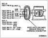
| Description: The powertrain control module controls the E4OD transmission operation through four on/off solenoids and one Variable Force Solenoid. These solenoids and transmission fluid temperature sensor are housed in the transmission solenoid body assembly. All are part of the transmission solenoid body and are not serviced individually. Additionally, in 1995, the protection diodes that were on the solenoid body have been moved to the PCM. Refer to the following information for the functions of these solenoids. |
The four on/off solenoids operate in the following manner.
Solenoid Operation

| Item | Description |
|---|---|
| 1 | Solenoid (Part of Transmission Solenoid Body) |
| 2 | Check Ball (Part of Solenoid) |
| 3 | Feed (Blocker) |
| 4 | Feed |
| 5 | Output (to Shift Valves, etc.) |

| Item | Description |
|---|---|
| 1 | Shift Solenoid 1 (Part of 7G391) |
| 2 | Shift Solenoid 2 (Part of 7G391) |
| 3 | Electronic Pressure Control Solenoid (Part of 7G391) |
| 4 | Coast Clutch Solenoid (Part of 7G391) |
| 5 | Transmission Fluid Temperature Sensor Location (Part of 7G391) |
| 6 | Torque Converter Clutch Solenoid (Part of 7G391) |

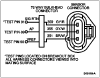
| 12-Way Connector Pin | Description | Connector Pin | ||
|---|---|---|---|---|
| EEC-V Gas | EEC-V Diesel | EEC-IV 5.8L (0/8,500 GVW) 7.5L (0/14,000 GVW) | ||
| 1 | Vehicle Power (VPWR) | 71, 97 | 71, 97 | 37, 57 |
| 2 | Shift Solenoid 2 | 1 | 1 | 19 |
| 3 | Shift Solenoid 1 | 27 | 27 | 52 |
| 4 | Torque Converter Clutch | 54 | 28 | 53 |
| 5 | Coast Clutch Solenoid | 53 | 53 | 55 |
| 6 | Ś | Ś | Ś | Ś |
| 7 | Transmission Fluid Temperature Sensor | 37 | 37 | 42 |
| 8 | Signal Return (SIG RTN) | 91 | 91 | 46 |
| 9 | Ś | Ś | Ś | Ś |
| 10 | Ś | Ś | Ś | Ś |
| 11 | Electronic Pressure Control | 81 | 81 | 38 |
| 12 | Electronic Pressure Control Power | 71, 97 | 71, 97 | 37, 57 |
| Description: The Electronic Pressure Control solenoid is a variable force solenoid. The variable-force type solenoid is an electro-hydraulic actuator combining a solenoid and a regulating valve. It supplies electronic pressure control which regulates transmission line pressure and line modulator pressure. This is done by producing resisting forces to the main regulator and the line modulator circuits. These two pressures control clutch application pressures. |
| Symptoms: Failed on Ś minimum electronic pressure control pressure (minimum transmission torque capacity). Limit engine torque (partial fuel shut-off, heavy misfire). Flashing transmission control indicator lamp. |
| Failed off Ś maximum electronic pressure control pressure, harsh engagements and shifts. May flash transmission control indicator lamp. |
| Diagnostic Trouble Codes: 624,* 625,* P1746,* P1747.* |
| CAUTION: The electronic pressure control pressure output from the variable force solenoid is NOT adjustable. Any modification to the electronic pressure control solenoid will affect the transmission warranty. (*Output circuit check, generated only by electrical condition.) |
| Torque converter clutch solenoid provides torque converter clutch control by shifting the converter clutch control valve to apply or release the torque converter clutch. |
| Symptoms: Failed on Ś engine stalls in drive at idle low speeds with brake applied or manual 2. Failed off Ś converter clutch never engages. May flash transmission control indicator lamp. |
| Diagnostic Trouble Codes: 629,* P0741,** P0743,** P1743, P1742, P1744. (*Output circuit check, generated only by electrical condition. **May also be generated by other non-electronic related transmission hardware condition.) |
| The Coast Clutch Solenoid provides coast clutch control by shifting the coast clutch shift valve. The solenoid is activated by pressing the transmission control switch or by selecting the 1 or 2 range with the transmission gearshift selector lever. In manual 1 and 2, the coast clutch is controlled by the solenoid and also hydraulically as a fail-safe to ensure engine braking. In reverse, the coast clutch is controlled hydraulically and the solenoid is not on. NOTE: On certain applications, the coast clutch is controlled by the PCM in the overdrive position (TCS OFF) in gears 1, 2, and 3. |
| Symptoms: Failed on Ś Third gear engine braking with (D) range selected. Failed off Ś No third gear engine braking in overdrive cancel. |
| Diagnostic Trouble Codes: 626,* 628,** 643,* 652,* P0741,** P0743,* P1754.* |
| (*Output circuit check, generated only by electrical conditions. **May also be generated by other non-electronic related transmission hardware condition.) |
| Shift solenoids 1 and 2 provide gear selection of first through fourth gears by controlling the pressure to the three shift valves. |
| Symptoms: Improper gear selection depending on failure mode and manual lever position; refer to the Shift Solenoid Operation Chart. May flash transmission control indicator lamp. |
| Diagnostic Trouble Codes: 617,** 618,** 619,** 621,* P0750,* P0751, P0781,** P0782,** P0783.** (*Output circuit check, generated only by electrical conditions. **May also be generated by other non-electronic related transmission hardware condition.) |
| Symptoms: Improper gear selection depending on failure mode and manual lever position; refer to the Shift Solenoid Operation Chart. May flash transmission control indicator lamp. |
| Diagnostic Trouble Codes: 617,** 618,** 619,** 622,* P0755,* P0781,** P0782,** P0783,** P0756. (*Output circuit check, generated only by electrical conditions. **May also be generated by other non-electronic related transmission hardware condition.) |
Shift Solenoid Operation Chart
The following solenoid application chart shows normal solenoid operation for given operating modes.
| Gearshift Selector Lever Position | Powertrain Control Module Commanded Gear | Shift Control Solenoid 1 | Shift Control Solenoid 2 | Torque Converter Clutch Solenoid | Coast Clutch Solenoid |
|---|---|---|---|---|---|
| Park | First | ON | OFF | OFF | OFF |
| Reverse | First | ON | OFF | OFF | OFF |
| Neutral | First | ON | OFF | OFF | OFF |
| (D) | First | ON | OFF | a | a |
| (D) | Second | ON | ON | a | a |
| (D) | Third | OFF | ON | a | a |
| (D) | Fourth | OFF | OFF | a | OFF |
| (D) Cancel | First Through Third Gear Only, Shift Solenoid 1, Shift Solenoid 2, and Torque Converter Clutch, Same As Overdrive, Coast Clutch Solenoid Always On. | ||||
| Manual 2 | Second | a | a | a | ON |
| Manual 1 | Second | OFF | OFF | OFF | ON |
| Manual 1 | First | ON | OFF | OFF | ON |
Transmission Vehicle Harness Connectors
Transmission Solenoid Body
| 12-Way Connector Pin | Description | Connector Pin | ||
|---|---|---|---|---|
| EEC-V Gas | EEC-V Diesel | EEC-IV 5.8L (0/8,500 GVW) 7.5L (0/14,000 GVW) | ||
| 1 | Vehicle Power (VPWR) | 71, 97 | 71, 97 | 37, 57 |
| 2 | Shift Solenoid 2 | 1 | 1 | 19 |
| 3 | Shift Solenoid 1 | 27 | 27 | 52 |
| 4 | Torque Converter Clutch | 54 | 28 | 53 |
| 5 | Coast Clutch Solenoid | 53 | 53 | 55 |
| 6 | Ś | Ś | Ś | Ś |
| 7 | Transmission Fluid Temperature Sensor | 37 | 37 | 42 |
| 8 | Signal Return (SIG RTN) | 91 | 91 | 46 |
| 9 | Ś | Ś | Ś | Ś |
| 10 | Ś | Ś | Ś | Ś |
| 11 | Electronic Pressure Control | 81 | 81 | 38 |
| 12 | Electronic Pressure Control Power | 71, 97 | 71, 97 | 37, 57 |
Transmission Range Sensor

| Pin Number | Circuit | Circuit Function |
|---|---|---|
| 1 | 57 (BK) | Ground Circuit |
| 2 | 359 (GY/R) | Sensor Signal Return |
| 3 | 199 (LB/Y) | Transmission Range Sensor to PCM |
| 4 | 463 (R/W) | Electronic Transfer Case Module to TR Sensor |
| 5 | 33 (W/PK) | Starter Circuit |
| 6 | 140 (BK/PK) | Backup Lamp |
| 7 | 298 (P/O) | Fused Accessory Feed |
| 8 | 32 (R/LB) | Starter Circuit |
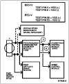
Transmission Control System Diagram, EEC-IV, 5.8L 0/8,500 GVW; 7.5L 0/14,000 GVW (Only)
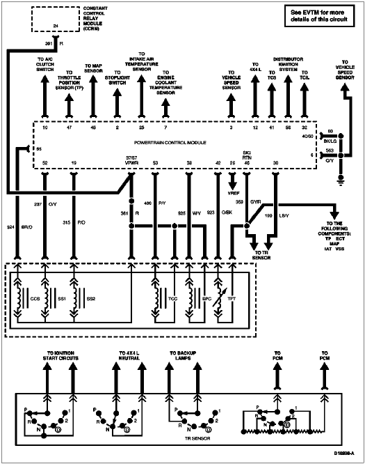
Transmission Control System Diagram, EEC-V Gas (Only)

Transmission Control System Diagram, EEC-V Diesel (Only)
