Like the preceding shaft check, the preload should be 0.02 to 0.11mm (0.00079 to 0.00434 inch) after installing the thrust washer.

Section 07-03B: Transmission, Manual, Model S5-47 ZF | 1996 F-Series Vehicles Over 8500 lbs. GVW Workshop Manual |
| Description | Tool Number |
|---|---|
| Clutch Housing Alignment Adapter | T75L-4201-A |
NOTE: Countershaft is serviced by Ford as an assembly only. Individual countershaft components will not be serviced.
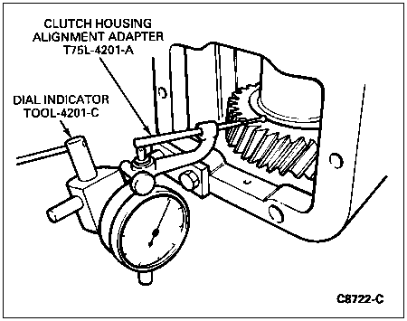
Using two 10mm hex screws, attach Dial Indicator with Bracketry TOOL-4201-C and Clutch Housing Alignment Adapter T75L-4201-A to the PTO opening in the case (7005) as shown in the illustration. Position the dial indicator gauge to the support in such a way that the measurement bar rests against the flat face of the fourth speed helical gear on the countershaft cluster gear (7113).
NOTE: Countershaft thrust washer (7119) under front bearing race must be removed prior to preload measurement.
Set the dial indicator needle to zero.
Insert pry bars through each of the two power take-off openings and position them beneath the 4th speed helical gear on the countershaft cluster gear. Pry up on the countershaft cluster gear.
Like the preceding shaft check, the preload should be 0.02 to 0.11mm (0.00079 to 0.00434 inch) after installing the thrust washer.

Mainshaft and Input Shaft Tapered Roller Bearing Preload Adjustment
| Description | Tool Number |
|---|---|
| Impact Slide Hammer | T50T-100-A |
After completing the tapered roller bearing preload measurements described previously, place the case in an upright position with the input shaft (7017) pointing upwards.
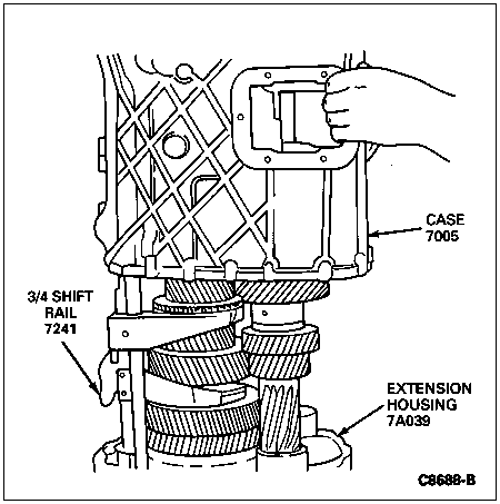
Drive the two dowel pins out of their holes in the case and extension housing (7A039) and lift the case off the extension housing.

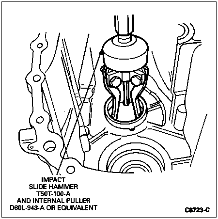
Using Impact Slide Hammer T50T-100-A and Internal Puller D80L-943-A or equivalent, remove the countershaft tapered roller bearing outer races and mainshaft tapered roller bearing outer races from the case.

NOTE: Always replace the baffle plate with a new one when removed.
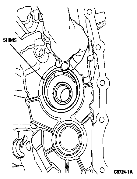
Fit each race with a shim washer or shim washer and baffle plate to obtain the required preload determined previously. Countershaft preload is established by using shims alone; input shaft and mainshaft preload is established by using shims and a baffle. In both cases the parts are installed beneath the outer race of the tapered roller bearing which seats in the case.

![]() CAUTION: Do not use silicone.
CAUTION: Do not use silicone.
Apply Gasket Maker E2AZ-19562-B or equivalent meeting Ford specification WSK-M2G348-A5 to the mating surfaces of the case and extension housing.
Position the case on the extension housing. Install all of the screws that secure the case and extension housing and tighten to 22 Nm (16 lb-ft).
Input shaft and mainshaft should turn freely by hand after preload adjustment.