Air Conditioning System
Section 12-03A: Air Conditioning System, Manual A/C-Heater | 1996 F-150, F-250, F-350, F-Super Duty and Bronco, F-Super Duty Motorhome Chassis Workshop Manual |
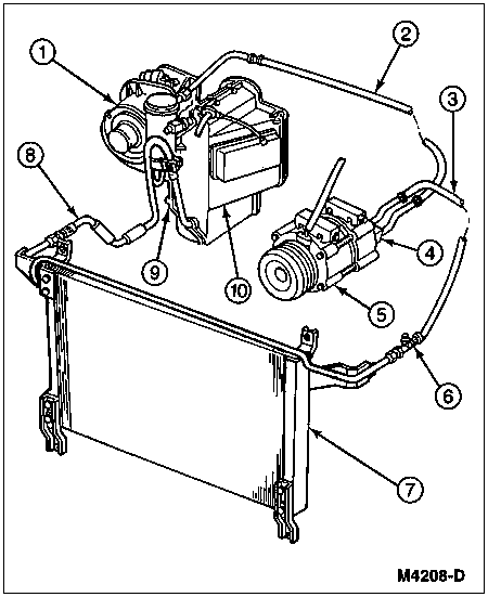
Most of the major components of the manual air conditioning/heater system are identified in the first three illustrations. The first is a diagram of a typical refrigerant circuit; the third is a disassembled view showing an A/C evaporator housing (19850) and a heater air plenum chamber (18471) positioned on opposite sides of the dash panel.
The system is equipped with:
Two quick disconnect R-134a service access gauge ports are used in the manual air conditioning/heater system. The high pressure gauge port is located near the A/C condenser core (19712) in the A/C manifold and tube (19D734) (discharge side) and has a quick disconnect-type valve body. This requires a special high pressure service access valve adapter (Rotunda R-134a High-Side Quick Disconnect E176-R0037 or equivalent) to connect a gauge set or a charging station to the port. The other service access gauge port is located on the inlet to the suction accumulator and also requires a quick disconnect-type adapter (Rotunda R-134a Low-Side Quick Disconnect 176-R0036 or equivalent). This fitting is used to measure pressure in the A/C evaporator core.
Air Conditioning System
| Item | Part Number | Description |
|---|---|---|
| 1 | 18527 | Blower Motor |
| 2 | Ś | Suction Line (Part of 19D734) |
| 3 | Ś | Discharge Line (Part of 19D734) |
| 4 | 19D734 | A/C Manifold and Tube |
| 5 | 19703 | A/C Compressor |
| 6 | Ś | High Pressure Service Valve (Part of 19972) |
| 7 | 19712 | A/C Condenser Core |
| 8 | 19835 | Condenser to Evaporator Tube |
| 9 | 19930 | A/C Blower Housing |
| 10 | 19B735 | A/C Evaporator Case Cover |
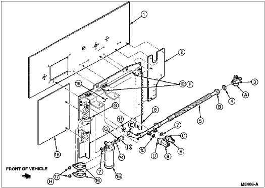
| Item | Part Number | Description |
|---|---|---|
| 1 | 19T554 | A/C Condenser Seal (Upper) |
| 2 | 19T557 | A/C Condenser Seal (LH) |
| 3 | 19762 | A/C Compressor Discharge Valve Assembly |
| 4 | 391397-S100 | O-Ring (0.405 x 0.076) |
| 5 | 19972 | A/C Compressor to Condenser Discharge Line |
| 6 | 19D594 | A/C Pressure Cut-Off Switch |
| 7 | 391396-S100 | O-Ring (0.295 x 0.74) |
| 8 | 19N656 | A/C Condenser Bracket |
| 9 | 19E561 | A/C Cycling Switch |
| 10 | N807083-S | O-Ring (8.15 x 2.0) |
| 11 | 391397-S100 | O-Ring (0.405 x 0.076) |
| 12 | N606691-S2 | Bolt (M8 x 1.25 x 35) |
| 13 | 19947 | A/C Dehydrator and Receiver Coupling |
| 14 | N807114-S | O-Ring (9.37 x 1.85) |
| 15 | 19959 | A/C Dehydrator and Receiver Tank |
| 16 | 19B937 | A/C Dehydrator Tank Mounting Bracket |
| 17 | 34659-S36 | Nut and Washer (1/4-20) |
| 18 | 19T556 | A/C Condenser Seal |
| 19 | 19712 | A/C Condenser Core |
| A | Ś | Tighten to 32-40 Nm (24-30 Lb-Ft) |
| B | Ś | Tighten to 53-67 Nm (39-49 Lb-Ft) |
| C | Ś | Tighten to 7-13 Nm (62-115 Lb-In) |
| D | Ś | Tighten to 1.5 Nm (18 Lb-In) |
| E | Ś | Tighten to 15-17 Nm (11-13 Lb-Ft) |
| F | Ś | Tighten to 21-32 Nm (15-24 Lb-Ft) |
| G | Ś | Tighten to 15-18 Nm (11-13 Lb-Ft) |
| H | Ś | Tighten to 7-9 Nm (62-80 Lb-In) |
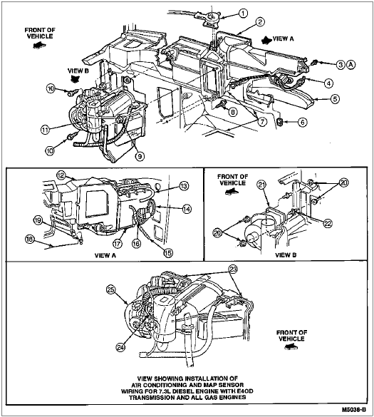
System Block Diagram
| Item | Part Number | Description |
|---|---|---|
| 1 | 19988 | A/C Temperature Cable |
| 2 | 18471 | Heater Air Plenum Chamber |
| 3 | 56950-S2 | Screw |
| 4 | 18C581 | A/C Plenum Vacuum Harness |
| 5 | 18C433 | Heater Outlet Floor Duct |
| 6 | 45261-S2 | J-Nut |
| 7 | 01610 | Dash Panel |
| 8 | 56956-S2 | Screw |
| 9 | N801969-S2 | Nut |
| 10 | 56956-S2 | Hex Screw and Washer Assembly |
| 11 | Ś | Locator (Part of 14401) |
| 12 | 18471 | Heater Air Plenum Chamber |
| 13 | Ś | Attaches to (Part of 18471) FAO End Item |
| 14 | Ś | Wiring Retainer (Part of 18456) |
| 15 | Ś | Locator (Part of 14401) |
| 16 | Ś | Wiring (Part of 18456) |
| 17 | Ś | Control Vacuum Harness (Part of 19C827) |
| 18 | 18C433 | Heater Outlet Floor Duct |
| 19 | N803946-S | Rivet |
| 20 | N612906-S2 | Nut |
| 21 | 18A484 | Heater Plenum Chamber Case |
| 22 | N803912-S2 | Stud |
| 23 | Ś | Retention Tab (Part of 19D674) |
| 24 | N801696-S2 | Nut |
| 25 | 18527 | Blower Motor |
| A | Ś | Tighten to 2.5-3.0 Nm (22-27 Lb-In) |
The A/C evaporator case (19897) is attached to the engine side of the dash panel. It contains the:
The suction accumulator/drier is clamped to the A/C evaporator case with its inlet tube connected to the outlet tube. The air conditioner A/C cycling switch is installed to a fitting on the side of the suction accumulator/drier. The inlet tube to the A/C evaporator core contains the A/C evaporator core orifice tube.