Section 17-01: Lighting, Exterior | 1996 F-150, F-250, F-350, F-Super Duty Motorhome and Bronco Workshop Manual |
DIAGNOSIS AND TESTING
Component Tests, Turn Signal Lamps/Hazard Flasher Lamps
NOTE: Use Rotunda 73 Digital Multimeter 105-R0051 or equivalent when performing the following component tests.
Turn Signal/Windshield Wiper Switch
Disconnect multi-function switch (13K359) wiring harness connector.
Attach ohmmeter to switch terminals.
Cycle switch as required to test all functions of terminals under test.
NOTE: Closed circuit is 5 ohms or less resistance between terminals.
Component testing procedures are provided to determine whether a component is good or bad.
Testing information for each component includes a schematic with component terminal locations and step-by-step test procedures. Component terminals are identified by:
- the circuit number of the wires that connect to that terminal;
- the wire insulation color; and
- letters or numbers that may be marked on the component.
The component connector MUST BE REMOVED before testing. To test a single circuit within the component, select that circuit under the column TO TEST. If you wish to test the complete component, perform all tests.
Connect the tester to the terminals shown in the second column and operate the component as shown in the third column.
COMPONENT TESTING PROCEDURE
| To Test | Connect Self-Powered Test Lamp or Ohmmeter to Terminals | Move Switch to These Positions | A Good Switch Will Indicate |
|---|
| Washer Switch Circuit | 590 (DB/W) and 993 (BR/W) | With Wiper Switch OFF: Push Washer Switch in. | Closed Circuit |
| | | Release Washer Switch. | 103.3k ohm |
| Wiper Switch Circuit | 589 (O) and 993 (BR/W) | Off
Interval
Low
High | 47.6k ohm
11.33k ohm
4.08k ohm
Closed Circuit |
| Interval Time Adjust | 590 (DB/W) and 993 (BR/W) | Interval and Off | Rotate Control Toward OFF; Ohmmeter Will Show Smoothly Increasing Resistance from 3.3k ohm Minimum to 103.3k ohm Maximum. |
| | | Low and High | 3.3k ohm |
| Flash-to-Pass | 196 (DB/O) and 12 (LG/BK)
15 (R/Y) and 13 (R/BK) | Lever Stalk Pull and Hold Toward Steering Wheel. | Closed Circuit |
| Dimmer HI Beam | 15 (R/Y) and 12 (LG/BK) | Lever Stalk Away from Steering Wheel. | Closed Circuit |
| Dimmer LO Beam | 15 (R/Y) and 13 (R/BK) | Lever Stalk in Detent Closest to Steering Wheel. | Closed Circuit |
| Turn Switch Circuit | 44 (LB) and 9 (LG/O),
44 (LB) and 3 (LG/W) | Turn Switch to TURN LEFT and Hazard Switch to OFF. | Closed Circuit |
| | 44 (LB) and 5 (O/LB),
44 (LB) and 2 (W/LB) | Turn Switch to TURN RIGHT and Hazard Switch to OFF. | Closed Circuit |
| Stoplamp Feed-Through Circuit | 511 (LG) and 9 (LG/O)
511 (LG) and 5 (O/LB) | Turn Switch to Center (No Turn) and Hazard Switch to OFF. | Closed Circuit |
Hazard Flasher Lamp Switch
Disconnect multi-function switch wiring harness connector.
Attach ohmmeter to switch terminals.
Cycle switch as required to test all functions of terminals under test.
NOTE: Closed circuit resistance between terminals is 5 ohms or less.
COMPONENT TESTING PROCEDURE
| To Test | Connect Self-Powered Test Lamp or Ohmmeter to Terminals | Move Switch to These Positions | A Good Switch Will Indicate |
|---|
| Hazard Switch | 385 (W/R) and 2 (W/LB),
5 (O/LB),
3 (LG/W), 9 (LG/O) | Hazard Switch ON (Button Depressed then Released to FULL OUT Position). | Closed Circuit |
Outside Rearview Mirror, Turn Signal Display, Bronco
Operate left and right turn signals and hazard flasher. Observe mirror signal display by standing alongside and slightly rearward of the vehicle. The signal display should not be evaluated from directly behind the vehicle. If the signal mirror display is inoperative, verify proper wiring connections and circuit continuity. Replace signal wiring as necessary. If the signal wiring tests OK, then replace the signal mirror glass assembly.
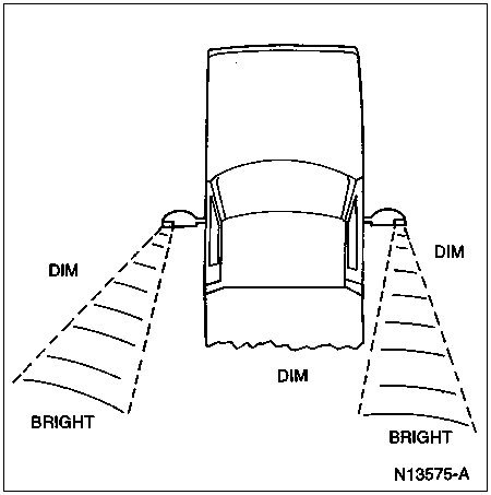
Examine the signal mirror display in natural light (outdoors). Signal brightness is affected by the amount of light shining onto mirror surface by an internal light sensor. When evaluating brightness side to side, make sure one mirror is not shaded more than the other, as this will cause one signal to appear brighter than the other. Note that the signal's bright zone on the passenger's side is further inboard than on the driver's side of the vehicle. Refer to the following illustration for normal signal display appearance.

Observe the signal display from the driver's seat with mirrors and seat adjusted to normal driving position. If the signal display is visible, the control circuit is malfunctioning. Replace the signal mirror glass assembly.
