
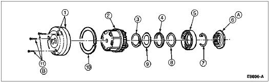
Section 05-03C: Wheel Hubs and Bearings, Front Wheels, 4-Wheel Drive | 1997 F-250 Heavy Duty and F-350 Workshop Manual |
| Item | Part Number | Description |
|---|---|---|
| 1 | 3A329 | Halfshaft |
| 2 | 3C132 | Rolling Diaphragm Seal (RDS), Axle |
| 3 | 3299 | Integral Spacer Needle Bearing Seal |
| 4 | 3123 | Bearing, Caged Needle |
| 5 | 3105 | Front Wheel Spindle |
| 6 | 1190 | Wheel Hub Grease Seal |
| 7 | 4221 | Inner Wheel Bearing (with Bearing Cup 4222) |
| 8 | 1102 | Front Disc Brake Hub and Rotor |
| 9 | 4221 | Outer Wheel Bearing (Bearing Cup 4222) |
| 10 | 3B549 | Wheel Retainer Key |
| 11 | Ś | Steel Thrust Washer (Part of 3B458) |
| 12 | Ś | Splined Thrust Washer (Part of 3B458) |
| 13 | Ś | Lock Ring (Part of 1K106) |
| 14 | 1K104 | Capscrew |
| 15 | 1K104 | Cap |
| 16 | 1K105 | Hub Body |
| 17 | 3B457 | Snap Ring |
| 18 | Ś | Plastic Thrust Washer (Part of 3B458) |
| 19 | Ś | Cam Assy (Part of 1K105) |
| 20 | Ś | Wheel Retainer (Nut) (Part of 1K105) |
| A | Ś | Tighten to 4-6 Nm (35-53 Lb-In) |
| B | Ś | While Rotating Front Disc Brake Hub and Rotor, Tighten to 68 Nm (50 Lb-Ft) to Seat Wheel Bearings. Back Nut Off 90 Degrees (1/4 Turn). Tighten to 1.8 Nm (16 Lb-In) |
Removal
![]() CAUTION: Do not drop hub components during removal and installation.
CAUTION: Do not drop hub components during removal and installation.
Separate cap from body assembly by removing the three capscrews from the cap, using Torx® bit TX25 or equivalent.
Remove cap.
Remove the lock ring seated in the groove of the front disc brake hub and rotor (1102).
Remove the body assembly from the front disc brake hub and rotor.
Automatic Locking Hub, Disassembled View, Typical
| Item | Part Number | Description |
|---|---|---|
| 1 | 1K104 | Cap |
| 2 | 1K105 | Hub Body |
| 3 | 3B457 | Snap Ring |
| 4 | Ś | Plastic Thrust Washer (Part of 3B458) |
| 5 | Ś | Cam Assy (Part of 1K105) |
| 6 | Ś | Wheel Retainer (Nut) (Part of 1K105) |
| 7 | 3B549 | Wheel Retainer Key |
| 8 | Ś | Steel Thrust Washer (Part of 3B458) |
| 9 | Ś | Splined Thrust Washer (Part of 3B458) |
| 10 | Ś | Lock Ring (Part of 1K104) |
| 11 | 1K104 | Capscrews (3) |
| A | Ś | While Rotating Front Disc Brake Hub and Rotor, Tighten Wheel Retainer (Nut) to 68 Nm (50 Lb-Ft) to Seat Wheel Bearings. Back Nut Off 90 Degrees (1/4 Turn). Tighten to 1.8 Nm (16 Lb-In). |
| B | Ś | Tighten to 4-6 Nm (35-53 Lb-In) |
Remove C-washer or snap ring from half shaft groove.
Remove spacers (three thrust washers) from shaft.
Remove cam assembly. Pull to remove.
If front disc brake hub and rotor and front wheel spindle (3105) are to be removed, refer to Wheel Grease Seal and Bearing, Front Replacement and Repacking, in the Disassembly and Assembly portion of this section.
Installation
Align the fixed cam retaining key on the cam assembly (garter spring inboard) with the keyway on the spindle. Firmly press the cam assembly on the wheel retainer nut.
![]() CAUTION: Improper sequence of three-piece thrust washers will result in excessive wear of assembly.
CAUTION: Improper sequence of three-piece thrust washers will result in excessive wear of assembly.
Install three-piece thrust washer set (first metal, second plastic, third splined) and snap ring. It may be necessary to push the axle outboard from backside of knuckle. Be sure snap ring is seated in groove properly.
![]() CAUTION: Rotate moving cam stop (use any one of three) to the one o'clock position in relationship to the fixed cam retaining key.
CAUTION: Rotate moving cam stop (use any one of three) to the one o'clock position in relationship to the fixed cam retaining key.
![]() CAUTION: Do not force body assembly into front disc brake hub on rotor if body assembly will not fit. Recheck alignment of all components.
CAUTION: Do not force body assembly into front disc brake hub on rotor if body assembly will not fit. Recheck alignment of all components.
NOTE: The hubs should not be packed with grease. Too much grease will damage the hubs and prevent proper operation.
Install body assembly into vehicle front disc brake hub and rotor by lining up the three legs outside the hublock body with the three pockets in the cam assembly.
Make sure body assembly is in far enough to see groove in rotor tube. Install large lock ring into groove of hub. Be sure lock ring is correctly seated.
Install cap to body assembly. Install three capscrews and tighten to 4-6 Nm (35-53 lb-in).