1994 PCED OBDI-A | SECTION 20A: Diesel Diagnosis—7.3L IDI Engine |
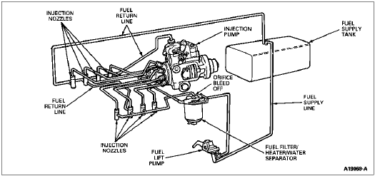
Figures 22 and 23 show schematics of the fuel supply and return lines. Fuel from the tank is routed to the fuel supply pump which pumps fuel through a combination fuel filter, heater system and water separator. The filter header contains a continuous vent (orifice bleed-off system) which aids starting by eliminating the need to manually prime the fuel filter. A vacuum switch is incorporated into the fuel filter header which will activate a light on the instrument panel indicating the need for filter replacement. The water separator portion of the filter assembly has a probe which will activate an instrument panel light when the filter requires draining at the water and sediment drain located on the bottom of the assembly.
Fuel enters the inlet of the injection pump and is delivered under high pressure through injection nozzles into the engine cylinders for combustion. On each nozzle is a fuel return fitting that returns excess fuel to the fuel tank. Excess fuel from the injection pump and each injection nozzle are collected in bleed-off lines and returned to the fuel tank.
The fuel return crossover line on the 7.3L IDI turbo diesel engine runs from the #5 injector tee to #6 injector tee, in front of the air chamber.

