Section 07-01B: Transmission, Automatic, C6 | 1996 F-250 4x2 and 4x4; F-350 4x2 and 4x4 Workshop Manual |
DIAGNOSIS AND TESTING
Special Testing Procedures
Engine Idle Speed Check
If the idle speed is too low, the engine will run roughly. An idle speed that is too high will cause the vehicle to creep, have harsh engagements and harsh closed-throttle downshifts.
Refer to the Powertrain Control/Emissions Diagnosis Manual OBDI or OBDII if you suspect an idle problem.
Shift Linkage Checks
Check shift linkage, downshift linkage and vacuum lines for proper adjustment and installation.
Downshift Cable Linkage
With the accelerator pedal held in the wide-open throttle position (at the floor), check throttle body lever and linkage travel to be sure they have attained full wide-open throttle. At the wide-open throttle position, the transmission downshift outer lever must move to the open position. At idle, it must return to the closed position. Refer to Section 10-02.
Manual Shift Cable
This is a CRITICAL adjustment. Be sure the D detent in the transmission corresponds exactly with the D gatestop in the steering column or console. Refer to Section 07-05 for adjustment procedures for the shift indicator cable.
- Internal hydraulic leakage at the manual shift valve can cause delay in engagements and/or slipping while operating if the external linkage is not correctly adjusted.
- Please note that the column-mounted PRNDL is adjustable. Once the transmission shift cable has been properly adjusted, the PRNDL can be adjusted to correspond exactly to the transmission shift cable adjustment.
Governor Test
The governor can be checked at the same time the Line Pressure Test is performed and in the same manner.
NOTE: After each test, move the gearshift lever (7210) to N (neutral) and run the engine at 1000 rpm to cool the transmission.
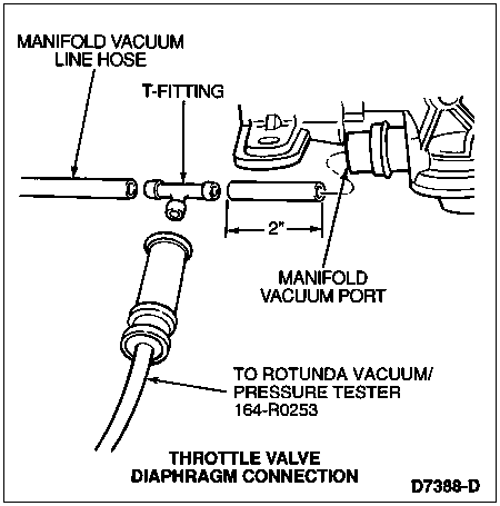
NOTE: Connect pump to throttle valve control diaphragm with a hose long enough to reach up to the driver's seat.
Raise the vehicle with an axle or frame hoist so that the rear wheels are clear of the floor.
Disconnect and plug the vacuum line to the throttle valve control diaphragm. Connect Vacuum Pump D83L-7059-A or equivalent to the throttle valve control diaphragm.
 CAUTION: Never exceed 96 km/h (60 mph) speedometer speed.
Place the transmission in D (drive), no load on the engine and apply 10 inches of vacuum to the throttle valve control diaphragm. Increase the speed slowly and watch the speedometer. Check the mph at which the control pressure cutback occurs. It should occur between 16-32 km/h (10-20 mph).
The governor is good if the cutback occurs within these specifications. If the cutback does not occur within specifications, check shift speeds to verify that it is the governor and not a stuck cutback valve, then repair or replace the governor.
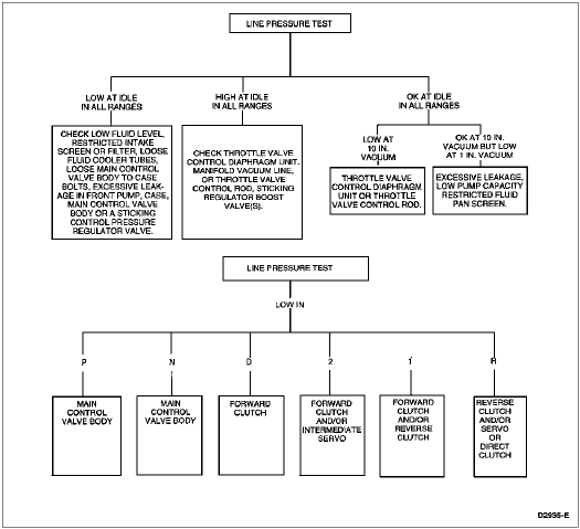
Line Pressure Test
There are two methods of performing the line pressure test. One is to perform the test using the engine vacuum. The second method is to use a remote vacuum source such as the one provided in the distributor tester or a hand-operated vacuum pump.
CAUTION: Perform line pressure test prior to performing stall speed test. If line pressure is low at stall, do not perform stall speed test or further transmission damage will occur. Do not maintain wide-open throttle in any gear range for more than five seconds.
This test verifies the line pressure is within specifications.
REFERENCE: LINE PRESSURE kPa (PSI) CHART NO. 401
| Transmission Model | Range | 51-57 kPa Vacuum (Idle) | 15-17 in-Hg Vacuum (Idle) | 34 kPa Vacuum (Part Throttle) | 10 in-Hg Vacuum (Part Throttle) | 1.7 kPa Vacuum (WOT Stall) | 0.5 in-Hg Vacuum (WOT Stall) |
|---|
| 4.9L Except 3.08 and 3.31 Axle, 5.0L Mexico and Venezuela, 7.5L | D, 2, 1
R
P, N | 345-552
448-862
345-552 | 50-80
65-125
50-80 | 621-793
965-1172
— | 90-115
140-170
— | 1103-1310
1724-1931
— | 160-190
250-280
— |
| All 4.9L with 3.08 or 3.31 Axle | D, 2, 1
R
P, N | 345-448
414-655
345-448 | 50-65
60-95
50-65 | 517-690
827-1034
— | 75-100
120-150
— | 1069-1276
1689-1896
— | 155-185
245-275
— |
| All 7.5L | D, 2, 1
R
P, N | 379-655
586-1000
379-655 | 55-95
85-145
55-95 | 690-827
1103-1276
— | 100-120
160-185
— | 1138-1310
1724-1931
— | 165-190
250-280
— |
REFERENCE: LINE PRESSURE (PSI) (HIGH ALTITUDE APPLICATIONS) NO. 401
| 82.5 kPa (24.5 in-Hg) Absolute Barometric Pressure (at 8047 km [5000 Ft.]) | Range | 51-57 kPa Vacuum Idle | 15-17 in-Hg Vacuum Idle | 34 kPa Part Throttle | 10 in-Hg Part Throttle | 1.7 kPa WOT Stall | 0.5 in-Hg WOT Stall |
|---|
| All with High Altitude Vacuum Throttle Valve Diaphragm (Aneroid) | D, 2, 1
R
P, N | 345-448
414-655
345-448 | 50-65
60-95
50-65 | 414-690
690-1034
— | 60-100
100-150
— | 896-1172
1413-1758
— | 130-170
205-255
— |
REFERENCE: LINE PRESSURE (PSI) (HIGH ALTITUDE APPLICATIONS) NO. 401 (Continued)
| 99 kPa (29.5 in-Hg) Absolute Barometric Pressure (at Sea Level) | Range | 51-57 kPa Vacuum Idle | 15-17 in-Hg Vacuum Idle | 34 kPa Part Throttle | 10 in-Hg Part Throttle | 1.7 kPa WOT Stall | 0.5 in-Hg WOT Stall |
|---|
| All with High Altitude Vacuum Throttle Valve Diaphragm (Aneroid) | D, 2, 1
R
P, N | 345-586
414-931
345-586 | 50-85
60-135
50-85 | 586-827
931-1241
— | 85-120
135-180
— | 1034-1310
1586-1931
— | 150-190
230-280
— |
Line Pressure Diagnosis Chart
Engine Vacuum Procedure
When the throttle control diaphragm is operating properly and the manual and downshift linkage is adjusted properly, all the transmission shifts (automatic and kickdown) should occur within the road speed limits listed in Specifications at the end of this section.
If the shifts do not occur within limits, or the transmission slips during shift point, use the following procedure to determine whether the engine, transmission, linkage, throttle valve control diaphragm or main control valve body (7A100) is causing the condition.
CAUTION: Pressure gauges affect the shift quality of the transmission. Care should be taken NOT to accelerate or decelerate rapidly. Possible transmission failure could result.
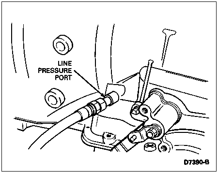
Attach a tachometer to the engine and a Rotunda Vacuum/Pressure Tester 164-R0253 or equivalent to the transmission vacuum line at the manifold vacuum port.
Attach a pressure gauge to the line pressure outlet at the transmission.
Firmly apply the parking brake and start the engine.
If the engine idle speed is not within specifications, refer to the Powertrain Control/Emissions Diagnosis Manual OBDI or OBDII for repair procedures. Also check throttle and downshift linkages for binding conditions.
- If linkage is satisfactory, check for vacuum leaks in the throttle valve control diaphragm and its connecting tubes and hoses. Check all other vacuum-operated units (such as the power brake) for vacuum leaks. Refer to the appropriate brake section in Group 06.
Vacuum Pump Procedure
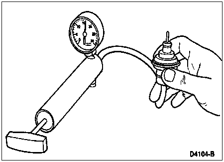
Disconnect and temporarily plug the vacuum line at the throttle valve control diaphragm. Attach a vacuum pump to the throttle valve control diaphragm.
Apply both the parking and service brakes. Start the engine and vacuum pump.
Set the vacuum at 15 inches, read and record the line pressure in all gearshift lever positions. Run the engine up to 1000 rpm, and reduce the vacuum to 10 inches. Read and record the line pressure in D, 2 and 1. Keep the engine rpm at 1000 and reduce the vacuum to 1 inch. Read and record the line pressure in D, 1, 2 and R.
Refer to the preceding Line Pressure Diagnosis Chart to show what components are inoperative when the line pressure test is not within specifications. Do not proceed until you have made any repairs, as required, and the control pressure is within specifications as listed in Specifications, at the end of this section.
Vacuum Supply Test
The vacuum supply to the throttle valve control diaphragm and the diaphragm itself must be checked.
Disconnect the vacuum line at the throttle valve control diaphragm and connect it to a vacuum gauge. With the engine idling, the gauge must have a steady acceptable vacuum reading 54-67.4 kPa (16-20 in-Hg) with the transmission in PARK (P).
- If the vacuum reading is low, check for a vacuum leak. If the vacuum reading is OK, rapidly accelerate the engine momentarily while applying the service brake and with the transmission in PARK. The vacuum reading must drop rapidly at acceleration and return immediately upon release of the accelerator. If the vacuum reading does not change or changes slowly, the transmission vacuum line is plugged, restricted or connected to a reservoir supply.
Correct as required.
Refer to the control pressure test diagnostic chart to show what components are inoperative when the control pressure test is not within specifications. Do not proceed until you have made any required repairs, and the control pressure is within specifications as listed in Specifications at the end of this section.
Vacuum Diaphragm Test
On-Vehicle Procedure
NOTE: If automatic transmission fluid is present in the vacuum side of the throttle valve control diaphragm or in the vacuum hose, the throttle valve control diaphragm is leaking and must be replaced.
To check the throttle valve control diaphragm, start the vacuum pump and set the regulator knob so that the vacuum gauge reads 18 inches with the end of the vacuum hose blocked off.
Connect the vacuum hose to the throttle valve control diaphragm. If the gauge still reads 18 inches, the throttle valve control diaphragm is not leaking. If the reading does not remain at 18 inches, but drops, the throttle valve control diaphragm is leaking. Remove vacuum throttle valve diaphragm heat shield and replace the throttle valve control diaphragm. Reinstall throttle valve control diaphragm heat shield.
Off-Vehicle Procedure
To check the throttle valve control diaphragm for diaphragm leakage, remove the unit from the transmission. Use a distributor tester equipped with Rotunda Vacuum Tester 014-R1054 or equivalent vacuum pump. Set the regulator knob until the vacuum gauge reads 18 inches with the end of the vacuum hose blocked off.
Connect the vacuum hose to the manifold vacuum port as shown previously. If the gauge still reads 18 inches, the throttle valve control diaphragm is not leaking. A second leakage check can be made as the hose is removed from the transmission. Hold a finger over the end of the control rod. When the hose is removed, the internal spring of the vacuum unit should push the throttle control valve rod (7A380) outward. If the vacuum diaphragm needs replacing, install a new unit modulator assembly that has been released for service. Reinstall the vacuum throttle valve diaphragm heat shield. Throttle valve control diaphragm assembly identification is given at end of this section. Refer to Vacuum Diaphragm Assembly Specification Chart in Specifications portion at the end of this section.
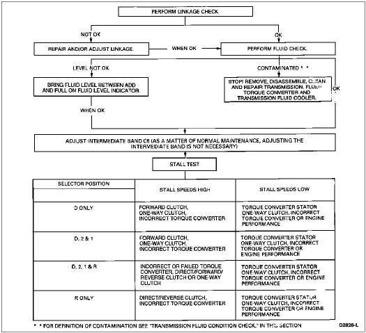
Stall Speed Test
WARNING: APPLY THE SERVICE AND PARKING BRAKES FIRMLY WHILE PERFORMING EACH STALL TEST.
CAUTION: Perform line pressure test prior to performing stall test. If line pressure is low at stall, do not perform stall test or further transmission damage will occur.
NOTE: The stall test should only be performed with the engine and transmission at normal operating temperatures.
The stall test checks the operation of the following items:
- torque converter one-way clutch
- forward clutch
- one-way clutch
- reverse clutch
- engine performance
Connect tachometer to engine.
After testing each of the following ranges, D, 2, 1 and R, move gearshift lever to N (neutral) and run engine for about 15 seconds to allow torque converter (7902) to cool before testing next range.
CAUTION: Do not maintain wide-open throttle (WOT) in any gear range for more than five seconds.
CAUTION: If engine rpm recorded by the tachometer exceeds maximum specified rpm, release accelerator pedal immediately. Clutch or band slippage is indicated.
Press accelerator pedal to floor wide-open throttle (WOT) in each range. Record rpm reached in each range. Stall speeds should be in appropriate range.
STALL SPEED CHART
| Vehicle | Axle Ratio | Engine Displacement | Stall Speed RPM |
|---|
| Min. | Max. |
|---|
| HD F-250/F-350 | 4.10 | 4.9L | 1589 | 1862 |
| HD F-250/F-350 | 3.55/4.10 | 5.8L | 2337 | 2750 |
| HD F-250/F-350 | 3.55/4.10 | 7.5L | 2012 | 2350 |
At the wide-open throttle position, the transmission downshift outer lever must move to the open position. At idle, it must return to the closed position. Refer to Section 10-02 for the engine throttle linkage adjustment procedure or replacement procedure.
Stall Speed Diagnosis Chart
Air Pressure Tests
NOTE: When you have a slip problem and do not know whether it is in the main control valve body or in the hydraulic system beyond the main control valve body, the air pressure tests can be very valuable.
To make the air pressure checks, loosen the transmission fluid pan bolts and lower one edge to drain the transmission fluid. Remove the transmission fluid pan and the main control valve body. The inoperative clutches or bands can be located by introducing air pressure into the various transmission case passages.
A no-drive condition can exist even with correct transmission fluid pressure because of inoperative clutches or bands. An erratic shift can be caused by a stuck governor primary valve. The inoperative units can be located through a series of checks by substituting air pressure for fluid pressure to determine the location of the malfunction.
When the gearshift lever is at D (drive), 2 (2nd) or L (low) a no-drive condition may be caused by an inoperative forward clutch or one-way clutch. Failure to drive in R (reverse) could be caused by a malfunction of the reverse clutch.
Case Fluid Passage Hole Identification
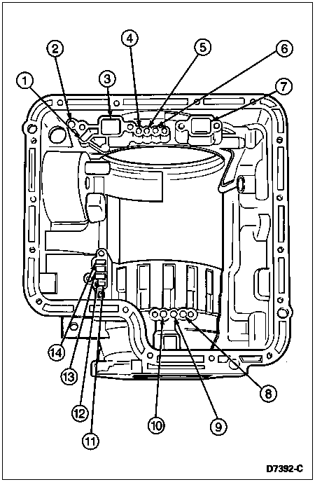
| Item | Part Number | Description |
|---|
| 1 | — | Servo Apply (Part of 7005) |
| 2 | — | Servo Release
(Part of 7005) |
| 3 | — | Pump Suction (Part of 7005) |
| 4 | — | Direct Clutch Apply
(Part of 7005) |
| 5 | — | Forward Clutch Cylinder Apply (Part of 7005) |
| 6 | — | Torque Converter Charge
(Part of 7005) |
| 7 | — | Pump Discharge
(Part of 7005) |
| 8 | — | Reverse Clutch Apply
(Part of 7005) |
| 9 | — | Control Pressure to Governor (Part of 7005) |
| 10 | — | Governor Pressure Output (Part of 7005) |
| 11 | — | Exhaust (Part of 7005) |
| 12 | — | Throttle Valve Pressure
(Part of 7005) |
| 13 | — | Line Pressure (Part of 7005) |
| 14 | — | Throttle Valve Pressure (Part of 7005) |
Reverse Clutch
Apply air pressure to the reverse clutch apply. A dull thud indicates that the reverse clutch piston (7D402) has moved to the applied position. If no noise is heard, place the fingertips on the case at reverse clutch and again apply air pressure to detect movement of the reverse clutch piston.
Forward Clutch
Apply air pressure to the transmission case forward clutch cylinder passage. A dull thud can be heard when the forward clutch piston is applied. If no noise is heard, place the fingertips on the input shell and again apply air pressure to the forward clutch cylinder passage. Movement of the forward clutch piston can be felt as the clutch is applied.
Governor
Apply air pressure to the control pressure-to-governor passage and listen for a sharp clicking or whistling noise. The noise indicates governor primary valve movement.
Intermediate Servo
Hold the air nozzle in the intermediate servo apply passage. Operation of the servo is indicated by a tightening of the intermediate band around the intermediate brake drum. Continue to apply air pressure to the servo apply or passage, and introduce air pressure into the intermediate servo release passage. The intermediate servo should release the intermediate band against the apply pressure.
PINPOINT TEST A: TRANSMISSION NOISY — OTHER THAN VALVE RESONANCE
A1 CHECK GEAR NOISE
- Check for gear noise to verify if within normal range.
Is noise within normal range?
| Yes | No |
|---|
| Normal condition. | GO to A2. |
A2 TRANSMISSION SHIFT CABLE AND BRACKET CHECK
- Check shift cable and bracket for proper adjustment, wear or damage.
Are shift cable and bracket OK?
| Yes | No |
|---|
| GO to A3. | SERVICE, REPLACE and/or ADJUST shift cable and bracket as required. |
A3 FLUID CHECK
- Check the fluid for proper level.
Is fluid at proper level?
| Yes | No |
|---|
| GO to A4. | ADD specified fluid to bring level between ADD and FULL marks with vehicle at operating temperature. GO to A4. |
A4 STALL TEST
- Perform the Stall Speed Test in the Diagnosis and Testing portion of this section.
Does noise stop?
| Yes | No |
|---|
| GO to A5. | EXAMINE torque converter and front pump assembly. SERVICE or REPLACE as required. Also CHECK for loose torque converter-to-flywheel bolts or nuts. |
A5 NOISE CHECK
- Run transmission in all gears and check for noise.
Is noise still present?
| Yes | No |
|---|
| SERVICE both planet assemblies as required. | Problem not in transmission. REFER to Section 00-04 for further noise diagnosis. |
Park/Neutral Position Switch Tests
Verify park/neutral position switch is adjusted properly in neutral. Refer to Park/Neutral Position Switch Adjustment in In-Vehicle Service portion of this section. For diagnostic procedures, refer to Section 07-14B.
Road test vehicle to confirm customer concern.