1994 PCED OBDI-A | SECTION 6A: EEC-IV Pinpoint Test
Procedures |
DQ1 DIAGNOSTIC TROUBLE CODE (DTC) 23:
CHECK FOR STUCK THROTTLE LINKAGE
Note: If you are directed here because of a Key On Engine Running (KOER) DTC 23, but an Engine ID Code of 5.0 was not received, then go directly to Pinpoint Test Step DJ1.
- Visually inspect throttle linkage for binding or sticking.
- Verify the throttle linkage is at mechanical/closed throttle. Check for binding throttle linkage, speed control linkage, vacuum line/electrical harness interference, etc.
Does throttle move freely and return to closed throttle position?
DQ2 DTC 53:
ATTEMPT TO GENERATE DTC 63
- Key off.
- Disconnect TP sensor vehicle harness connector at the fuel injection pump. Inspect for damaged pins, corrosion, loose wires, etc. Service as necessary.
- Rerun Key On Engine Off (KOEO) Self-Test.
Is DTC 63 present (ignore all other DTCs)?
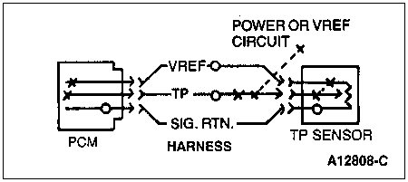
DQ3 CHECK VREF CIRCUIT VOLTAGE
- Key off.
- TP sensor disconnected.
- Key on, engine off.
- Measure voltage between VREF circuit and SIG RTN circuit at the TP sensor vehicle harness connector.
Is voltage between 4.0 and 6.0 volts?
| Yes | No |
|---|
| RECONNECT all components. GO to DQ14 for TP sensor adjustment procedures. | RECONNECT all components. GO to Pinpoint Test Step C1. |
DQ4 CHECK TP CIRCUIT FOR SHORT TO POWER
- Key off, wait 10 seconds.
- TP sensor disconnected.
- Disconnect PCM. Inspect for damaged or pushed out pins, corrosion, loose wires, etc. Service as necessary.
- Install breakout box, leave PCM disconnected.
- Measure resistance between Test Pin 47 and Test Pins 26 and 57 at the breakout box.
Is each resistance greater than 10,000 ohms?
| Yes | No |
|---|
| REPLACE PCM. REMOVE breakout box. RECONNECT TP sensor. RERUN Quick Test. | SERVICE short circuit. REMOVE breakout box. RECONNECT all components. RERUN Quick Test. |
DQ10 DTC 63:
ATTEMPT TO GENERATE DTC 53/23
- Key off.
- Disconnect TP sensor vehicle harness connector at throttle body. Inspect for damaged or pushed out pins, corrosion, loose wires, etc. Service as necessary.
- Jumper VREF circuit to TP circuit at TP sensor vehicle harness connector.
- Perform Key On Engine Off (KOEO) Self-Test.
Note: If no DTCs are generated, immediately remove jumper and go directly to DQ13.
Is DTC 53 or 23 present (ignore all other DTCs)?
| Yes | No |
|---|
| REMOVE jumper wire. RECONNECT TP sensor. GO to DQ14 for TP sensor adjustment procedures. | GO to DQ11. |
DQ11 CHECK VREF CIRCUIT VOLTAGE
- Key off.
- TP sensor disconnected.
- Key on, engine off.
- Measure voltage between VREF circuit and SIG RTN circuit at the TP sensor vehicle harness connector.
Is voltage between 4.0 and 6.0 volts?
| Yes | No |
|---|
| GO to DQ12. | RECONNECT all components. GO to Pinpoint Test Step C1. |
DQ12 CHECK TP CIRCUIT CONTINUITY
- Key off.
- TP sensor disconnected.
- Disconnect PCM. Inspect for damaged or pushed out pins, corrosion, loose wires, etc. Service as necessary.
- Install breakout box and connect PCM to breakout box.
- Measure resistance between TP circuit at the TP sensor vehicle harness connector and Test Pin 47 at the breakout box.
Is the resistance less than 5.0 ohms?
| Yes | No |
|---|
| GO to DQ13. | SERVICE open circuit. REMOVE breakout box. RECONNECT all components. RERUN Quick Test. |
DQ13 CHECK TP CIRCUIT FOR SHORTS TO GROUND
- Key off.
- TP sensor disconnected.
- Disconnect PCM. Inspect for damaged or pushed out pins, corrosion, loose wires, etc. Service as necessary.
- Install breakout box, leave PCM disconnected.
- Measure resistance between Test Pin 47 and Test Pins 40, 46, and 60 at the breakout box.
Is each resistance greater than 10,000 ohms?
| Yes | No |
|---|
| REPLACE PCM. REMOVE breakout box. RECONNECT all components. RERUN Quick Test. | SERVICE short circuit. REMOVE breakout box. RECONNECT all components. RERUN Quick Test. |
DQ14 CHECK TP SENSOR ADJUSTMENT
Note: Two people are required to perform this procedure.
- Perform KOEO Self-Test while holding the throttle wide open (WOT).
- After last Diagnostic Trouble Code (DTC) has been displayed, remain in Self-Test.
- While in Self-Test, place 0.515 inch gauge block Rotunda T83T-7B200-AH between Fuel Pump Lever Travel Screw and Gauge Boss (Figures 1 and 2).
- Cycle the Transmission Cancel Switch (TCS) once.
- Observe Self-Test Output (STO) of the STAR tester for:
- Constant tone, solid light, or "STO LO" readout means the TP sensor adjustment is within range. Cycle TCS to get out of this test.
- Beeping tone, flashing light, or "STO LO" erratic readout (four per second) indicates adjustment is required.
- Beeping tone, flashing light, or "STO LO" erratic readout (one per second) indicates adjustment is required.
- If tone is undetectable, TP sensor may have worn internal substrate. Check by trying to move sensor.
- If adjustment is required, refer to Figure 3.
- If TP sensor and bracket screws are tight and there are no signs of wear between the mounted parts, loosen TP sensor attachment screws and rotate sensor one way or the other until a constant tone, solid light or "STO LO" readout is obtained. Tighten TP sensor attachment screws. REMOVE gauge block, RERUN Quick Test.
- If bracket shows signs of wear due to movement or vibration, remove epoxy from TP sensor bracket screw heads. Loosen screws and turn the TP sensor/bracket assembly to get within range. Then retighten screws and apply epoxy to screw head. REMOVE gauge block, RERUN Quick Test.
- If the DTCs are still present or a steady tone cannot be obtained, REPLACE the TP sensor.
 WARNING: DO NOT TURN THE FUEL PUMP LEVER TRAVEL SCREW. THIS SCREW HAS BEEN PRESET AND SHOULD NOT BE TAMPERED WITH.

Figure 1: Top View of Fuel Pump

Figure 2: Throttle Side View

Figure 3: TP Sensor Side View
DQ90 CONTINUOUS MEMORY DIAGNOSTIC TROUBLE CODE (DTC) 53: MONITOR TP CIRCUIT UNDER SIMULATED ROAD SHOCK
- Enter Key On Engine Off Continuous Monitor Diagnostic Test Mode (DTM). Refer to Quick Test Appendix, Section 5A.
- Observe VOM or STAR LED for indication of a fault while performing the following:
- Move throttle slowly to WOT position.
- Release throttle slowly to closed position and lightly tap on TP sensor (simulate road shock).
- Wiggle TP sensor harness connector.
Does VOM or STAR LED indicate a fault?
DQ91 MEASURE TP CIRCUIT VOLTAGE WHILE EXERCISING TP SENSOR
- Key off.
- VOM or STAR LED still connected to STO as in previous step.
- Disconnect Powertrain Control Module (PCM). Inspect for damaged or pushed out pins, corrosion, loose wires, etc. Service as necessary.
- Install breakout box and connect processor to breakout box.
- Connect a DVOM from Test Pin 47 to Test Pin 46 at the breakout box.
- Key on, engine off.
- While observing DVOM, repeat Step DQ90.
Does the fault occur below 4.25 volts?
| Yes | No |
|---|
DISCONNECT and INSPECT connectors. If connector and terminals are OK, GO
to DQ14. | VERIFY harness integrity, GO to DQ92. |
DQ92 CHECK EEC VEHICLE HARNESS
- Still in Key On Engine Off Continuous Monitor DTM.
- Observe VOM or STAR LED for a fault indication while performing the following:
- Referring to the illustration in Step DQ90, grasp the vehicle harness close to the sensor connector. Wiggle, shake or bend a small section of the EEC system vehicle harness while working toward the dash panel. Also wiggle, shake or bend the EEC vehicle harness from the dash panel to the processor.
Does VOM or STAR LED indicate a fault?
| Yes | No |
|---|
| ISOLATE fault. SERVICE as necessary. REFER to appropriate figure. CLEAR Continuous Memory (REFER to Quick Test Appendix, Section 5A). RERUN Quick Test. | GO to DQ93. |
DQ93 CHECK PCM AND HARNESS CONNECTORS
- Key off.
- Disconnect PCM. Inspect for damaged or pushed out pins, corrosion, loose wires, etc. Service as necessary.
Are connectors and terminals OK?
| Yes | No |
|---|
| Unable to duplicate and/or identify fault at this time. For further diagnosis using the EEC-IV Monitor box, REFER to Section 7A, EEC-IV Monitor box: Intermittent Fault Diagnosis. All others, CLEAR Continuous Memory (REFER to Quick Test Appendix, Section 5A). RERUN Quick Test. | SERVICE as necessary. CLEAR Continuous Memory (REFER to Quick Test Appendix, Section 5A). RERUN Quick Test. |
DQ94 CONTINUOUS MEMORY DIAGNOSTIC TROUBLE CODE (DTC) 63: MONITOR TP CIRCUIT UNDER SIMULATED ROAD SHOCK
Note: If DTCs 63/33 OR 33/63 were received during the Continuous Self-Test, GO to DQ97.
- Enter Key On Engine Off Continuous Monitor Diagnostic Test Mode (DTM). Refer to Quick Test Appendix, Section 5A.
- Observe VOM or STAR LED for indication of a fault while performing the following:
- Move throttle slowly to WOT position.
- Release throttle slowly to closed condition.
- Lightly tap on TP sensor (simulate road shock).
- Wiggle TP sensor vehicle harness connector.
Does VOM or STAR LED indicate a fault?

| Yes | No |
|---|
| INSPECT connectors. If connector and terminals are good, GO to DQ14. | GO to DQ95. |
DQ95 CHECK EEC VEHICLE HARNESS
- Still Key On Engine Off Continuous Monitor DTM.
- Observe VOM or STAR LED for a fault indication while performing the following:
- Refer to the illustration in Step DQ94. Grasp the vehicle harness close to the sensor connector. Wiggle, shake or bend a small section of the EEC system vehicle harness while working toward the dash panel. Also wiggle, shake or bend the EEC vehicle harness from the dash panel to the processor.
Does VOM or STAR LED indicate a fault?
| Yes | No |
|---|
| ISOLATE fault. SERVICE as necessary. REFER to appropriate figure. CLEAR Continuous Memory (REFER to Quick Test Appendix, Section 5A). RERUN Quick Test. | GO to DQ96. |
DQ96 CHECK PCM AND HARNESS CONNECTORS
- Key off.
- Disconnect PCM. Inspect for damaged or pushed out pins, corrosion, loose wires, etc.
Are connectors and terminals OK?
| Yes | No |
|---|
| Unable to duplicate and/or identify fault at this time. For further diagnosis using the EEC-IV Monitor box, REFER to Section 7A, EEC-IV Monitor box: Intermittent Fault Diagnosis. All others, CLEAR Continuous Memory (REFER to Quick Test Appendix, Section 5A). RERUN Quick Test. | SERVICE as necessary. CLEAR Continuous Memory (REFER to Quick Test Appendix, Section 5A). RERUN Quick Test. |
DQ97 DIAGNOSTIC TROUBLE CODE 33: TP NOISE
Note: DTC 33: (TP NOISE) is generated when the TP Sensor begins to deteriorate to the point where TP voltage may fluctuate at a constant throttle position.
- Possible Causes:
Is only DTC 33 present?
| Yes | No |
|---|
| REPLACE TP Sensor. RERUN Quick Test. | Testing complete:
RETURN to Diagnostic Routines if additional information is required. |
DQ100 DIAGNOSTIC TROUBLE CODE 43: TP BELOW IDLE, CHECK TP CIRCUIT CONTINUITY
Note: DTC 43 is intended to capture worn or misadjusted TP sensors. When TP voltage drops below the calibrated idle value, DTC 43 is set.
Possible causes:
- Increased resistance.
- Misadjusted TP sensor.
- Damaged TP sensor.
- Key off, wait 10 seconds.
- Disconnect PCM. Inspect for damage or pushed out pins, corrosion, loose wires, etc. Service as necessary.
- Install breakout box, leave PCM disconnected.
- Measure resistance between Test Pin 47 and Test Pins 40, 46, and 60 at the breakout box.
Is each resistance greater than 10,000 ohms?
| Yes | No |
|---|
| GO to DQ14. | SERVICE loose terminals or SERVICE short circuit. REMOVE breakout box. RECONNECT all components. RERUN Quick Test. |