Transmission Vehicle Harness Connector Pin Identification

Section 07-01A: Transmission, Automatic, E4OD | 1996 All F-Series and Bronco with E4OD Automatic Transmission Workshop Manual |
Use the following pinpoint tests to diagnose transmission electrical concern.
If DTCs are present while performing the On-Board Diagnostic, refer to Diagnostic Trouble Code Charts in the Diagnosis and Testing portion of this section for the appropriate service procedure.
NOTE: Prior to performing pinpoint tests, refer to any technical service bulletins and OASIS messages for E4OD transmission concerns.
NOTE: Prior to performing pinpoint tests, the vehicle harness must be checked for continuity and shorts; the powertrain control module (PCM) (12A650) must be checked for any concerns. Refer to the Powertrain Control/Emissions Diagnosis Manual OBDI or OBDII for proper procedures.
NOTE: If any nontransmission DTCs appear, service those codes first. They could affect the electrical operation of the transmission. Record and erase codes from continuous memory after service has been performed. After servicing any DTCs in the Quick Test, the Quick Test should be repeated.
NOTE: Check powertrain control module wiring harness for proper connections, bent or broken pins, corrosion, loose wires, proper routing, proper seals and their condition. Check the powertrain control module sensors and actuators for physical damage.
Diagnostic Trouble Codes:
NOTE: This pinpoint test is designed to diagnose the shift solenoid electrical system only. To prevent replacement of good components, note that the following areas may be at fault:
This pinpoint test is designed to diagnose the following components:
Refer to the following schematic and charts when performing the pinpoint test steps.
Transmission Vehicle Harness Connector Pin Identification
| Circuit | PCM Pin Number | ||
|---|---|---|---|
| EEC-V | EEC-IV 5.8L 0/8,500 GVW 7.5 0/14,000 GVW | 7.3L DI Diesel | |
| SS1 | 27 | 52 | 27 |
| SS2 | 1 | 19 | 1 |
| VPWR | 71, 97 | 37, 57 | 71, 97 |
SS1 = Shift Solenoid No. 1.
SS2 = Shift Solenoid No. 2.
| Gearshift Selector Lever Position | Powertrain Control Module Commanded Gear | Shift Control Solenoid 1 | Shift Control Solenoid 2 | Torque Converter Clutch Solenoid | Coast Clutch Solenoid |
|---|---|---|---|---|---|
| Park | First | ON | OFF | OFF | OFF |
| Reverse | First | ON | OFF | OFF | OFF |
| Neutral | First | ON | OFF | OFF | OFF |
| (D) | First | ON | OFF | a | a |
| (D) | Second | ON | ON | a | a |
| (D) | Third | OFF | ON | a | a |
| (D) | Fourth | OFF | OFF | a | OFF |
| (D) | Cancel | First Through Third Gear Only, Shift Solenoid 1, Shift Solenoid 2, and Torque Converter Clutch, Same as Overdrive, Coast Clutch Solenoid Always On. | |||
| Manual 2 | Second | a | a | a | ON |
| Manual 1 | Second | OFF | OFF | OFF | ON |
| Manual 1 | First | ON | OFF | OFF | ON |
Shift Solenoid Failure Mode Charts
Shift Control Solenoid Failure Always OFF
Failed OFF due to powertrain control module and/or vehicle wiring concerns; solenoid electrically or hydraulically stuck OFF.
| Powertrain Control Module Gear Commanded | Position Selected: Overdrive | Position Selected: 2 | Position Selected: 1 |
|---|---|---|---|
| Actual Gear Obtained | |||
| 1 | 4 | 2 | 1 |
| 2 | 3 | 2 | 2 |
| 3 | 3 | 2 | 2 |
| 4 | 4 | 2 | 2 |
| Powertrain Control Module Gear Commanded | Position Selected: Overdrive | Position Selected: 2 | Position Selected: 1 |
|---|---|---|---|
| Actual Gear Obtained | |||
| 1 | 1 | 2 | 1 |
| 2 | 1 | 2 | 1 |
| 3 | 4 | 2 | 2 |
| 4 | 4 | 2 | 2 |
Failed ON due to powertrain control module and/or vehicle wiring concerns; solenoid electrically or hydraulically stuck ON.
| Powertrain Control Module Gear Commanded | Position Selected: Overdrive | Position Selected: 2 | Position Selected: 1 |
|---|---|---|---|
| Actual Gear Obtained | |||
| 1 | 1 | 2 | 1 |
| 2 | 2 | 2 | 1 |
| 3 | 2 | 2 | 1 |
| 4 | 1 | 2 | 1 |
| Powertrain Control Module Gear Commanded | Position Selected: Overdrive | Position Selected: 2 | Position Selected: 1 |
|---|---|---|---|
| Actual Gear Obtained | |||
| 1 | 2 | 2 | 1 |
| 2 | 2 | 2 | 1 |
| 3 | 3 | 2 | 2 |
| 4 | 3 | 2 | 2 |
| Yes | No |
|---|---|
| REMAIN in Output State DTM. GO to A2. | DEPRESS throttle and release. If vehicle did not enter Output State DTM, REFER to Powertrain Control/Emissions Diagnosis Manual OBDI or OBDII. |
![]() CAUTION: Remove heat shield from transmission before removing connector. Remove solenoid body connector by pushing on center tab and pulling on wiring harness. Do not attempt to pry tab with a screwdriver. Reinstall heat shield after service.
CAUTION: Remove heat shield from transmission before removing connector. Remove solenoid body connector by pushing on center tab and pulling on wiring harness. Do not attempt to pry tab with a screwdriver. Reinstall heat shield after service.
NOTE: Refer to the schematic and charts preceding this pinpoint test.
| Yes | No |
|---|---|
| GO to A5. | GO to A3. |
NOTE: Refer to the schematic and charts preceding this pinpoint test.
| Yes | No |
|---|---|
| GO to A4. | SERVICE open circuit(s). REMOVE Breakout Box. RECONNECT all components. REPEAT Quick Test. |
NOTE: Refer to the schematic and charts preceding this pinpoint test.
| Yes | No |
|---|---|
| GO to A5. | SERVICE short circuit. REMOVE Breakout Box. RECONNECT all components. REPEAT Quick Test. |
NOTE: LED will turn green when solenoid activates and turn off when deactivated. LED will turn red if activated solenoid is shorted to B+. LED will remain off if an activated solenoid is shorted to ground or no continuity.
| Yes | No |
|---|---|
| GO to A6. | GO to A7. |
| Yes | No |
|---|---|
| ERASE all codes and PERFORM Transmission Drive Cycle Test in this section. REPEAT Quick Test. | GO to A7. |
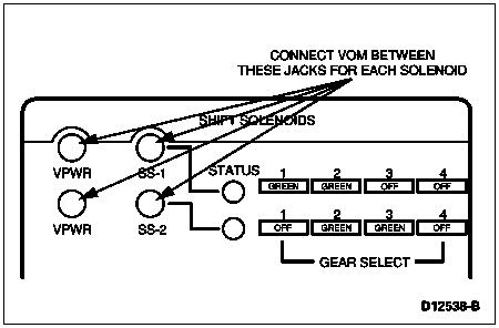
| Yes | No |
|---|---|
| GO to A8. | REPLACE solenoid body assembly. RECORD and ERASE codes. REPEAT Quick Test. |
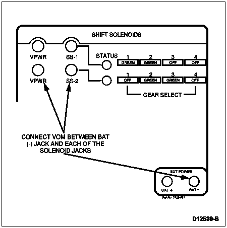
| Yes | No |
|---|---|
| REPLACE solenoid body assembly. RECORD and ERASE codes. REPEAT Quick Test. | GO to Diagnosis by Symptom. |
Diagnostic Trouble Codes:
NOTE: This pinpoint test is designed to diagnose the Transmission Fluid Temperature Sensor electrical system ONLY. To prevent replacement of good components, note that the following areas may be at fault:
This pinpoint test is designed to diagnose the following components:
Refer to the following schematic and charts when performing the pinpoint test steps.
Transmission Vehicle Harness Connector Pin Identification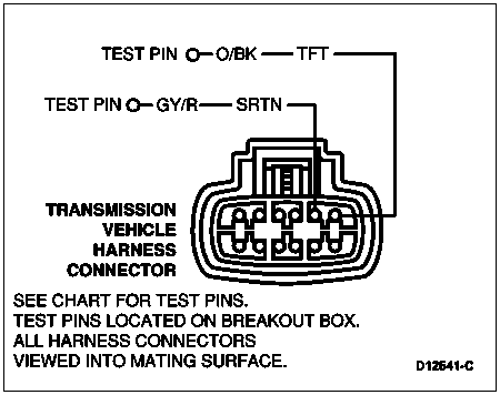
| Circuit | PCM Pin Number | |
|---|---|---|
| EEC-V | EEC-IV 5.8L 0/8,500 GVW 7.5L 0/14,000 GVW | |
| TFT | 37 | 42 |
| SRTN | 91 | 46 |
TFT = Transmission Fluid Temperature.
SRTN = Sensor Signal Return.
| Yes | No |
|---|---|
| GO to B2. | PERFORM checks. ERASE codes. REPEAT Quick Test. |
![]() CAUTION: Remove heat shield from transmission before removing connector. Remove solenoid body connector by pushing on center tab and pulling on wiring harness. Do not attempt to pry tab with a screwdriver. Reinstall heat shield after service.
CAUTION: Remove heat shield from transmission before removing connector. Remove solenoid body connector by pushing on center tab and pulling on wiring harness. Do not attempt to pry tab with a screwdriver. Reinstall heat shield after service.
NOTE: Refer to the schematic and chart preceding this pinpoint test.
| Yes | No |
|---|---|
| GO to B6. | GO to B3. |
NOTE: Refer to the schematic and chart preceding this pinpoint test.
| Yes | No |
|---|---|
| GO to B4. | SERVICE open circuit(s). REMOVE Breakout Box. RECONNECT all components. ERASE codes. REPEAT Quick Test. |
NOTE: Refer to the schematic and chart preceding this pinpoint test.
| Yes | No |
|---|---|
| GO to B5. | SERVICE short circuit. REMOVE Breakout Box. RECONNECT all components. ERASE codes. REPEAT Quick Test. |
NOTE: While performing Tests 1 and 2 observe resistances.
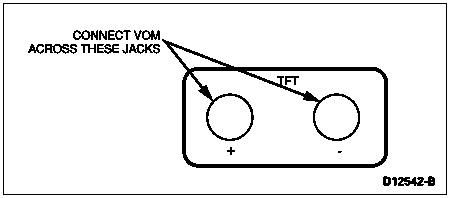
| °C | °F | Resistance (Ohms) |
|---|---|---|
| (-)40-(-)20 | (-)40-(-)4 | 967k-248k |
| (-)19-(-)1 | (-)3-31 | 248k-100k |
| 0-20 | 32-68 | 100k-37k |
| 21-40 | 69-104 | 37k-16k |
| 41-70 | 105-158 | 16k-5k |
| 71-90 | 159-194 | 5k-2.7k |
| 91-110 | 195-230 | 2.7k-1.5k |
| 111-130 | 231-266 | 1.5k-0.8k |
| 131-150 | 267-302 | 0.8k-0.54k |
| Yes | No |
|---|---|
| GO to B6. | REPLACE solenoid assembly. RECORD and ERASE codes. REPEAT Quick Test. |
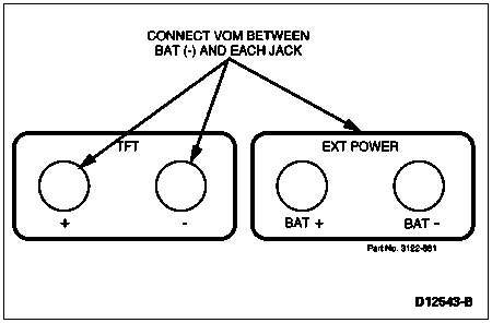
| Yes | No |
|---|---|
| REPLACE solenoid assembly. REPEAT Quick Test. | REPEAT Quick Test. If codes are present and overtemp condition existed, CHECK fluid condition. CHECK overheat condition under Diagnosis by Symptom. SERVICE as required. REPEAT Quick Test. |
Diagnostic Trouble Codes:
NOTE: This pinpoint test is designed to diagnose the Torque Converter Clutch Solenoid electrical system ONLY. To prevent replacement of good components, note that the following areas may be at fault:
This pinpoint test is designed to diagnose the following components:
Refer to the following schematic and charts when performing the pinpoint test steps.
Transmission Vehicle Harness Connector Pin Identification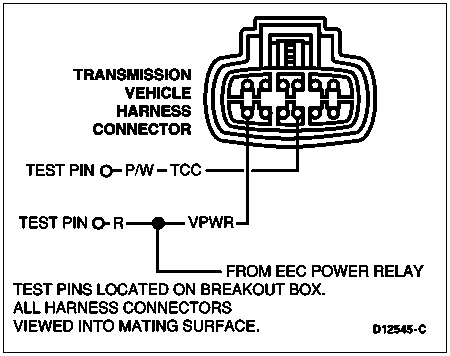
| Circuit | PCM Pin Number | |
|---|---|---|
| EEC-V | EEC-IV 5.8L 0/8,500 GVW 7.5L 0/14,000 GVW | |
| TCC | 54 28 (Diesel) | 53 |
| Yes | No |
|---|---|
| REMAIN in Output State DTM. GO to C2. | DEPRESS throttle and RELEASE. If vehicle did not enter Output State DTM, REFER to Powertrain Control/Emissions Diagnosis Manual OBDI or OBDII. |
![]() CAUTION: Remove heat shield from transmission before removing connector. Remove solenoid body connector by pushing on center tab and pulling on wiring harness. Do not attempt to pry tab with a screwdriver. Reinstall heat shield after service.
CAUTION: Remove heat shield from transmission before removing connector. Remove solenoid body connector by pushing on center tab and pulling on wiring harness. Do not attempt to pry tab with a screwdriver. Reinstall heat shield after service.
NOTE: Refer to the schematic and chart preceding this pinpoint test.
| Yes | No |
|---|---|
| GO to C5. | GO to C3. |
NOTE: Refer to the schematic and chart preceding this pinpoint test.
| Yes | No |
|---|---|
| GO to C4. | SERVICE open circuit(s). REMOVE Breakout Box. RECONNECT all components. REPEAT Quick Test. |
NOTE: Refer to the schematic and chart preceding this pinpoint test.
| Yes | No |
|---|---|
| GO to C5. | SERVICE short circuit. REMOVE Breakout Box. RECONNECT all components. REPEAT Quick Test. |
NOTE: LED will turn green when solenoid activates and turn off when deactivated. LED will turn red if activated solenoid is shorted to B+. LED will remain off if an activated solenoid is shorted to ground or no continuity.
| Yes | No |
|---|---|
| GO to C6. | GO to C7. |
| Yes | No |
|---|---|
| REPLACE PCM. PERFORM Transmission Drive Cycle Test in this section. REPEAT Quick Test. If symptoms are still present, REFER to Torque Converter Clutch Operation Concerns, under Diagnosis by Symptom, in the Diagnosis and Testing portion of this section. | GO to C7. |
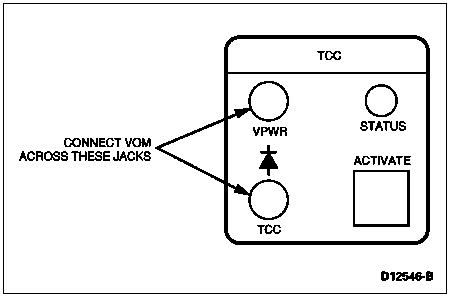
| Yes | No |
|---|---|
| GO to C8. | REPLACE solenoid body assembly. |
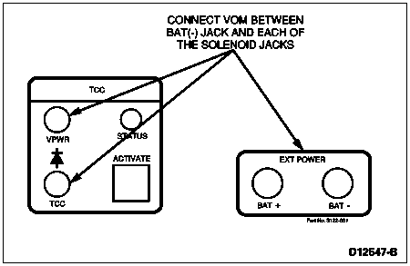
| Yes | No |
|---|---|
| REPLACE solenoid body assembly. | GO to Diagnosis by Symptom Index for torque converter clutch diagnosis. |
Diagnostic Trouble Codes:
NOTE: This pinpoint test is designed to diagnose the TR Sensor electrical system ONLY. To prevent replacement of good components, note that the following areas may be at fault:
This pinpoint test is designed to diagnose the following components:
Refer to the following schematic and charts when performing the pinpoint test steps.
Transmission Range (TR) Sensor Schematic and Connector Pin Identification
| Pin Number | Circuit | Circuit Function |
|---|---|---|
| 1 | 57 (BK) | Ground Circuit |
| 2 | 359 (GY/R) | Sensor Signal Return |
| 3 | 199 (LB/Y) | Transmission Range Sensor to PCM |
| 4 | 463 (R/W) | Electronic Transfer Case Module to TR Sensor |
| 5 | 33 (W/PK) | Starter Circuit |
| 6 | 140 (BK/PK) | Backup Lamp |
| 7 | 298 (P/O) | Fused Accessory Feed |
| 8 | 32 (R/LB) | Starter Circuit |
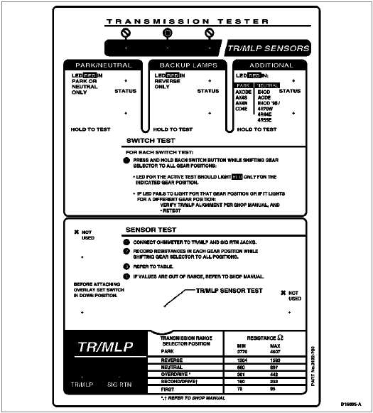
NOTE: Additional codes may also be set by running Quick Tests with the transmission not in PARK or with the A/C on. Make sure Quick Tests are performed properly.
| Yes | No |
|---|---|
| REMOVE tool. GO to D2. | ADJUST sensor. REFER to Section 07-14A. After adjustments, PLACE transmission gearshift selector lever in PARK. CLEAR DTCs and REPEAT Quick Test. |
![]() CAUTION: Do not pry on connector. Pull up on vehicle harness connector.
CAUTION: Do not pry on connector. Pull up on vehicle harness connector.
NOTE: Refer to the schematic preceding this pinpoint test.
| Yes | No |
|---|---|
| GO to D5. | GO to D3. |
![]() CAUTION: Do not pry connector. Squeeze TABS and pull up on vehicle harness.
CAUTION: Do not pry connector. Squeeze TABS and pull up on vehicle harness.
NOTE: Refer to the schematic preceding this pinpoint test.
| Yes | No |
|---|---|
| GO to D4. | SERVICE open circuit(s). REMOVE Breakout Box. RECONNECT all components. ERASE codes. REPEAT Quick Test. |
NOTE: Refer to the schematic preceding this pinpoint test.
| Yes | No |
|---|---|
| GO to D5. | SERVICE short circuit. REMOVE Breakout Box. RECONNECT all components. ERASE codes. REPEAT Quick Test. |
| Transmission Range Selector Lever Position | Resistance (Ohms) Min. | Resistance (Ohms) Max. | Range Volts |
|---|---|---|---|
| P | 3770 | 4607 | 3.97-4.85 |
| R | 1304 | 1593 | 3.24-3.96 |
| N | 660 | 807 | 2.55-3.11 |
| D | 361 | 442 | 1.88-2.30 |
| 2 | 190 | 232 | 1.23-1.51 |
| 1 | 78 | 95 | 0.61-0.75 |
| Yes | No |
|---|---|
| If sent here directly from Step D2, GO to Step D6. If sent here from Step D4, REPLACE PCM, then GO to D6. | REPLACE TR sensor and ADJUST. REFER to Section 07-14A. ERASE codes and REPEAT Quick Test. |
| To Test | Ohmmeter to Terminals | Move Range Selector Lever to These Positions | A Good Sensor Will Indicate |
|---|---|---|---|
| Starter Relay Circuit | 33 (W/PK) and 32 (R/LB) | Park | Less than 5 ohms |
| Reverse | Greater Than 100k ohms | ||
| Neutral | Less than 5 ohms | ||
| (D) | Greater than 100k ohms | ||
| Second (2) | Greater than 100k ohms | ||
| First (1) | Greater than 100k ohms |
| Yes | No |
|---|---|
| GO to D7. If diagnosing a Park/Neutral circuit or starting concern, REFER to the appropriate service manual sections. | REPLACE the TR sensor and adjust. REFER to Section 07-14A. ERASE DTCs and RERUN Quick Test. |
| To Test | Ohmmeter to Terminals | Move Range Selector Lever to These Positions | A Good Sensor Will Indicate |
|---|---|---|---|
| Backup Lamp Circuit | 298 (BK) and 140 (BK/PK) | Park | Greater than 100k ohms |
| Reverse | Less than 5.0 ohms | ||
| Neutral | Greater than 100k ohms | ||
| (D) | Greater than 100k ohms | ||
| Second (2) | Greater than 100k ohms | ||
| First (1) | Greater than 100k ohms |
| Yes | No |
|---|---|
| GO to D8. If diagnosing only a Reverse/Backup circuit concern, REFER to the appropriate service manual section. | REPLACE the TR sensor and adjust. REFER to Section 07-14A for procedures. ERASE DTCs and RERUN Quick Test. |
| To Test | Ohmmeter to Terminals | Move Range Selector Lever to These Positions | A Good Sensor Will Indicate |
|---|---|---|---|
| 4x4 Low — Neutral Sense Circuit | 463 (R/W) and 57 (BK) | Park | Greater than 100k ohms |
| Reverse | Greater than 100k ohms | ||
| Neutral | Less than 5.0 ohms | ||
| (D) | Greater than 100k ohms | ||
| Second (2) | Greater than 100k ohms | ||
| First (1) | Greater than 100k ohms |
| Yes | No |
|---|---|
| The concern is not in the sensor. If you were directed here from the Diagnosis by Symptom, RETURN to Routine. If you were here diagnosing a DTC, REFER to the Powertrain Control/Emissions Diagnosis Manual OBDI or OBDII to diagnose intermittent concerns. If diagnosing an optional circuit concern,REFER to the appropriate service manual sections. | REPLACE the TR sensor and adjust. REFER to In-Vehicle Service in this section for procedures. ERASE DTCs and RERUN Quick Test. |
Diagnostic Trouble Codes:
NOTE: This pinpoint test is designed to diagnosis the electronic pressure control solenoid electrical system ONLY. To prevent replacement of good components, note that the following areas may be at fault:
This pinpoint test is designed to diagnose the following components:
Refer to the following schematic and charts when performing the pinpoint test steps.
Transmission Vehicle Harness Connector Pin Identification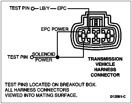
| Circuit | PCM Pin Number | |
|---|---|---|
| EEC-V | EEC-IV 5.8L 0/8,500 GVW 7.5L 0/14,000 GVW | |
| EPC | 81 | 38 |
| EPC PWR | 71, 97 | 37, 57 |
EPC = Electronic Pressure Control.
| Yes | No |
|---|---|
| REMAIN in Output State DTM. GO to E2. | DEPRESS throttle and release. If vehicle did not enter Output State DTM, REFER to Powertrain Control/Emissions Diagnosis Manual OBDI or OBDII. |
![]() CAUTION: Remove heat shield from transmission before removing connector. Remove solenoid body connector by pushing on center tab and pulling on wiring harness. Do not attempt to pry tab with a screwdriver. Reinstall heat shield after service.
CAUTION: Remove heat shield from transmission before removing connector. Remove solenoid body connector by pushing on center tab and pulling on wiring harness. Do not attempt to pry tab with a screwdriver. Reinstall heat shield after service.
NOTE: Refer to the schematic and chart preceding this pinpoint test.
| Yes | No |
|---|---|
| GO to E5. | GO to E3. |
NOTE: Refer to the schematic and chart preceding this pinpoint test.
| Yes | No |
|---|---|
| GO to E4. | SERVICE open circuit. REMOVE Breakout Box. RECONNECT all components. ERASE codes and REPEAT Quick Test. |
NOTE: Refer to the schematic and chart preceding this pinpoint test.
| Yes | No |
|---|---|
| GO to E5. | SERVICE short circuit. REMOVE Breakout Box. RECONNECT all components. REPEAT Quick Test. |
NOTE: Vehicle must be running.
| Yes | No |
|---|---|
| REPLACE powertrain control module. REPEAT Quick Test. | GO to E6. |
![]() CAUTION: Be sure that tester power is OFF or damage to volt-ohmmeter may result.
CAUTION: Be sure that tester power is OFF or damage to volt-ohmmeter may result.
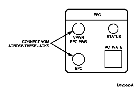
| Yes | No |
|---|---|
| GO to E7. | REPLACE solenoid body assembly. RECORD and ERASE codes. REPEAT Quick Test. |
| Solenoid | Tester Jack |
|---|---|
| Electronic Pressure Control | Electronic Pressure Control (EPC) Vehicle Power (VPWR) |
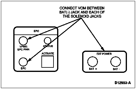
| Yes | No |
|---|---|
| REPLACE solenoid body assembly. RECORD and ERASE codes. REPEAT Quick Test. | GO to Diagnosis by Symptom Index for diagnosis of electronic pressure control concerns. |
Diagnostic Trouble Codes:
NOTE: This pinpoint test is designed to diagnosis the Coast Clutch Solenoid electrical system ONLY. To prevent replacement of good components, note that the following areas may be at fault:
This pinpoint test is designed to diagnose the following components:
Refer to the following schematic and charts when performing the pinpoint test steps.
Transmission Vehicle Harness Connector Pin Identification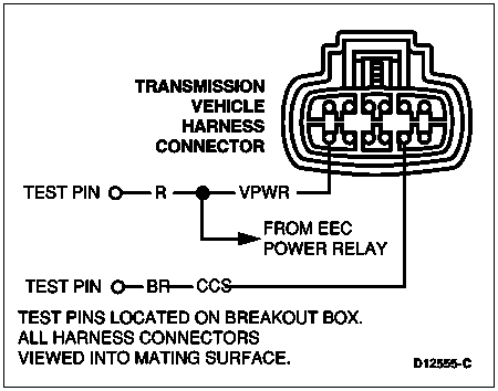
| Circuit | PCM Pin Number | |
|---|---|---|
| EEC-V PCM Pins | EEC-IV PCM Pins 5.8L 0/8,500 GVW 7.5L 0/14,000 GVW | |
| CCS | 53 | 55 |
| PWR | 71, 97 | 37, 57 |
CCS = Coast Clutch Solenoid.
| Yes | No |
|---|---|
| REMAIN in Output State DTM. GO to G2. | DEPRESS throttle and RELEASE. If vehicle still does not enter Output State DTM, REFER to Powertrain Control/Emissions Diagnosis Manual OBDI or OBDII. |
![]() CAUTION: Remove heat shield from transmission before removing connector. Remove solenoid body connector by pushing on center tab and pulling on wiring harness. Do not attempt to pry tab with a screwdriver. Reinstall heat shield after service.
CAUTION: Remove heat shield from transmission before removing connector. Remove solenoid body connector by pushing on center tab and pulling on wiring harness. Do not attempt to pry tab with a screwdriver. Reinstall heat shield after service.
NOTE: Refer to the schematic and chart preceding this pinpoint test.
| Yes | No |
|---|---|
| GO to G5. | GO to G3. |
NOTE: Refer to the schematic and chart preceding this pinpoint test.
| Yes | No |
|---|---|
| GO to G4. | SERVICE open circuit(s). REMOVE Breakout Box. RECONNECT all components. REPEAT Quick Test. |
NOTE: Refer to the schematic and chart preceding this pinpoint test.
| Yes | No |
|---|---|
| GO to G5. | SERVICE short circuit. REMOVE Breakout Box. RECONNECT all components. REPEAT Quick Test. |
NOTE: LED will turn green when solenoid activates and turn off when deactivated. LED will turn red if activated solenoid is shorted to B+. LED will remain off if an activated solenoid is shorted to ground or no continuity.
| Yes | No |
|---|---|
| GO to G6. | GO to G7. |
| Yes | No |
|---|---|
| ERASE all codes and PERFORM Transmission Drive Cycle Test in this section. REPEAT Quick Test. | GO to G7. |
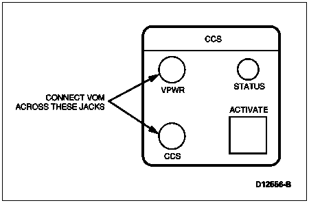
| Yes | No |
|---|---|
| GO to G8. | REPLACE solenoid body assembly. |
| Solenoid | Tester Jack |
|---|---|
| Coast Clutch Solenoid | Coast Clutch Solenoid (CCS) |
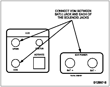
| Yes | No |
|---|---|
| REPLACE solenoid body assembly. | GO to Diagnosis by Symptom section for coast clutch concerns. |