1994 PCED OBDI-A | SECTION 6A: EEC-IV Pinpoint Test
Procedures |
H1 CHECK FOR FUEL DILUTED ENGINE OIL
| Diagnostic Trouble Code (DTC) | HO2S Orientation | Fault Definition |
|---|
172r
136r
176c | right or rear
left or front
left or front | system indicates lean |
173r
137r
177c | right or rear
left or front
left or front | system indicates rich |
144c
139c | right or rear
left or front | no HO2S switch
detected |
171c
175c | right or rear
left or front | adaptive fuel limit
reached |
- Possible Causes:
- Fuel injectors.
- HO2S.
- Secondary Air Injection (AIR) system.
- PCV/Hose.
- Vacuum.
- CANP.
- MAP sensor.
- Electronic Ignition Coil Failure.
- Key off.
- Remove the PCV valve from the valve cover. Inspect both rocker cover hole and PCV for damage, sludge build up, blockage and movement of valve plunger. Service as necessary.
- Run Key On Engine Off (KOEO) and Key On Engine Running (KOER) Self-Tests.
- Address any continuous ignition DTCs before servicing KOER DTCs.
Note: For a No Start, GO directly to H2.
Are any of the above DTCs present in KOER Self-Test?
| Yes | No |
|---|
| REINSTALL PCV valve. GO to H2. | For Continuous Memory DTCs 139, 144, 171, 176,177
GO to H2
AllOthers:
CHANGE engine oil and filter. REINSTALL PCV valve. DRIVE vehicle 5 miles/55mph. RERUN Quick Test. |
H2 CHECK FUEL PRESSURE
 WARNING: THE FUEL SYSTEM WILL REMAIN PRESSURIZED WHEN ENGINE IS NOT RUNNING. TO PREVENT INJURY OR FIRE USE CAUTION WHEN WORKING ON THE FUEL SYSTEM.
- Key off.
- Install fuel pressure gauge.
- Verify that manifold vacuum is connected to the fuel pressure regulator if applicable.
- If engine will start:
- Start and run engine at idle. Note fuel pressure.
- Increase engine speed to 2500 rpms and maintain for one minute. Note fuel pressure.
- Refer to Fuel Pressure Specification Table.
- If engine will not start:
- Cycle the key off and on several times. Note fuel pressure.
- Refer to Fuel Pressure Specification Table.
Is fuel pressure within specification for the engine being tested?
| Yes | No |
|---|
| GO to H3. | REFER to Section 9A Diagnostic Test Step FDS5. |
H3 CHECK SYSTEM'S ABILITY TO HOLD FUEL PRESSURE
- Pressurize fuel system per step H2.
- Visually look for fuel leaking at the injector O-ring, fuel pressure regulator, and the fuel lines to the fuel charging assembly. Service as necessary.
- Key on, engine off.
Does fuel pressure remain at specification for 60 seconds?
| Yes | No |
|---|
For No Starts:
GO to H4.For Service Codes or other Symptoms:
MFI: GO to H5.
SFI: GO to H6. | REFER to Section 9A, Diagnostic Test Step FDS3. |
H4 FUEL DELIVERY TEST
- Key off.
- Fuel pressure gauge installed.
- Pressurize fuel system per step H2.
- Locate and disconnect the Inertia Fuel Shutoff (IFS) switch.
- Crank engine for five seconds.
Does pressure drop more than 5 psi (34 kPa) by the end of the five second crank cycle?
| Yes | No |
|---|
| The EEC system is not the cause of the No Start. REMOVE the fuel pressure gauge. RECONNECT the IFS switch. REFER to Section 2A for further diagnosis. | REMOVE fuel pressure gauge. RECONNECT IFS switch.
For MFI:
GO to H7.For SFI:
GO to H8. |
H5 CYLINDER BALANCE DIAGNOSTIC TEST MODE (DTM): MFI ENGINES
- Connect tachometer to engine. Run engine at idle.
- Disconnect and reconnect the injectors one at a time: Note rpm drop for each injector.
Does each injector produce a momentary drop in rpm?
Note: IAC will attempt to reestablish rpm.
| Yes | No |
|---|
| For Symptoms RETURN to Section 2A. For DTCs 136, 172, 176:
GO to H13. For DTCs 137, 173, 177:
GO to H24. For all others:
GO to H14. | GO to H7. |
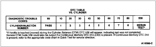
H6 CYLINDER BALANCE DIAGNOSTIC TEST MODE (DTM): SFI ENGINES
The DTM switches each injector OFF and ON one at a time. Diagnostic Trouble Codes (DTC) correspond to the cylinder number (i.e., Service DTC 30 indicates a problem with cylinder No. 3, a DTC 90 indicates a pass.) The Cylinder Balance (DTM) is designed to aid in the detection of a weak or non-contributing cylinder. The Pinpoint Test Steps are designed to isolate only EEC related problems.
Refer to Quick Test Appendix, Section 5A, for detailed information about Cylinder Balance (DTM).
- Run the Engine Running Self-Test.
- After the last repeated code, wait 5-10 seconds.
- "Goose" throttle lightly (not wide-open-throttle).
- Cylinder Balance (DTM) will be performed. Time of test is approximately 2-3 minutes.
Note: If KOER DTC 244 (for 2.0L Probe only) is output, Cylinder Balance DTM has been aborted, immediately go to Pinpoint Test Step DR1.
Are there any cylinder balance DTCs requiring service?
| Yes | No |
|---|
| GO to H8. | For Symptoms RETURN to Section 2A. For DTC 136, 172, 176:
GO to H13. For DTC 137, 173, 177:
GO to H24. For all others:
GO to H14. |
H7 CHECK RESISTANCE OF INJECTOR(S) AND HARNESS MFI ENGINES
Is each resistance within specification for the appropriate engine?
| Yes | No |
|---|
| GO to H12. | For NO START:
SERVICE open in VPWR circuit.For others:
GO to H9. |
H8 CHECK RESISTANCE OF INJECTOR(S) AND HARNESS SFI ENGINES
Is each resistance within specification for the appropriate engine?
| Yes | No |
|---|
| GO to H12. | For NO START:
SERVICE open in VPWR circuit.For others:
GO to H9. |
H9 CHECK CONTINUITY OF FUEL INJECTOR HARNESS
- Key off.
- Breakout box installed, PCM disconnected.
- Disconnect injector vehicle harness connector at the suspect injector.
- Measure resistance between Test Pin 37/57 at the breakout box and the VPWR pin at the injector vehicle harness connector.
- Refer to the Pinpoint Test Schematic for the appropriate injector pin identification.
- Measure resistance between the injector test pin(s) at the breakout box and the same injector circuit signal pin at each injector vehicle harness connector.
Is each resistance less than 5.0 ohms?
| Yes | No |
|---|
| GO to H10. | SERVICE open circuit. REMOVE breakout box. RECONNECT PCM and injectors.
DRIVE vehicle 5 miles/55 mph.
RERUN Quick Test. |
H10 CHECK INJECTOR HARNESS CIRCUIT FOR SHORT TO POWER OR GROUND
- Key off.
- Breakout box installed, PCM disconnected.
- Suspect fuel injector vehicle harness disconnected.
- Refer to the Pinpoint Test Schematic for the appropriate injector pin identification.
- Measure resistance between the injector test pin(s) and Test Pins 37/57, 40, 46 and 60 at the breakout box.
- Measure resistance between the injector test pin(s) at the breakout box and chassis ground.
Is each resistance greater than 10,000 ohms?
| Yes | No |
|---|
For SFI:
REPLACE injector per Cylinder Balance DTM fault code. RERUN Quick Test.For MFI:
GO to H11. | SERVICE short circuit. REMOVE breakout box. RECONNECT PCM and injectors. DRIVE vehicle 5 miles/55 mph. RERUN Quick Test. |
H11 ISOLATE FAULTY INJECTOR CIRCUIT
- Key off.
- Breakout box installed, PCM disconnected.
- Disconnect all injectors on suspect bank.
- DVOM on 200 ohm scale.
- Connect one injector and measure resistance between Test Pin 37 and either Test Pin 58 or 59 as appropriate.
- Disconnect that injector and repeat process for each of the remaining injectors.
- Refer to Injector Resistance Specification Table 2.
Is each resistance within specification for the appropriate engine?
| Yes | No |
|---|
| GO to H12. | REPLACE injector. REMOVE breakout box. RECONNECT PCM and injectors. DRIVE vehicle 5 miles/55 mph. RERUN Quick Test. |
H12 CHECK INJECTOR DRIVER SIGNAL
Requires standard nonpowered 12 volt test lamp.
- Key off.
- Breakout box installed.
- Connect PCM to breakout box.
- For MFI:
- Connect test lamp between Test Pin 37 and Test Pin 58 at the breakout box.
- Connect test lamp between Test Pin 37 and 59 at the breakout box.
- For SFI:
- Connect test lamp between Test Pin 37 and the suspect injectors Test Pin at the breakout box.
- Crank or start engine.
Note: Properly operating systems will show a dim glow on the lamp.
Is glow on lamp dim?
| Yes | No |
|---|
| REMOVE breakout box. RECONNECT PCM. Follow instructions for injector testing in Section 9A. Also refer to Ignition Section for other possible causes. After any servicing, DRIVE vehicle 5 miles/55 mph. RERUN Quick Test and Cylinder Balance DTM. | No light/Bright light:
REPLACE PCM. REMOVE breakout box. DRIVE vehicle 5 miles/55 mph. RERUN Quick Test. |
H13 CHECK SECONDARY AIR INJECTION (AIR) OPERATION
Note: If vehicle is equipped with Pulsed-Secondary Air Injection (PAIR) or no AIR, ignore this step and GO to H14.
With dual HO2S, DTC 172 refer to right or rear HO2S; DTC 136, 176 refers to left or front HO2S.
HO2S always lean could be caused by:
- Thermactor air being diverted upstream from the HO2S.
- Key off.
- Disconnect the AIR hose(s) from the AIR pump so that secondary air is bypassed to atmosphere during testing.
- Run Engine Running Self-Test.
Are DTCs 136, 172, 176 present?
| Yes | No |
|---|
| RECONNECT AIR Hose. GO to H14. | For Continuous Memory DTCs 139, 144, 171, 176, 177:
GO to H90.
All Others:
GO to Section 13A for AIR systems diagnosis. |
H14 CHECK HO2S INTEGRITY
HO2S always lean, slow to switch or lack of switching. Fuel at adaptive limit could be caused by:
- Moisture inside the HO2S harness connector resulting in a short to ground.
- HO2S coated with contaminants.
- HO2S circuit open.
- HO2S circuit shorted to ground.
- Key off.
- Inspect the HO2S harness for chafing, burns or other indications of damage. Service as necessary.
- Inspect HO2S and connector for indication of submerging in water, oil, coolant, etc. Service as necessary.
- Run engine at 2000 rpm for two minutes.
- Key off.
- Run Engine Running Self-Test.
Are fault codes present?
| Yes | No |
|---|
For engines with
� MAP sensor: GO to H15.
� MAF sensor: GO to H16. | GO to H21. |
H15 CHECK HO2S ON ENGINES WITH MAP SENSORS
Note: Vacuum/air leaks in non-EEC areas could also cause DTCs 136, 172 or 176. Check for:
- Leaking vacuum actuator (e.g. A/C control motor).
- Engine sealing.
- EGR system.
- PCV system.
- Lead contaminated HO2S.
- Key off.
- Verify MAP sensor output voltage (refer to procedure in Pinpoint Test Step DF3).
- Disconnect appropriate HO2S from vehicle harness.
- For 4 wire HO2S (refer to schematic):
- Connect DVOM to HO2S circuit and HO2S GND or SIG RTN at the HO2S connector.
- For 3 wire HO2S (refer to schematic):
- Connect DVOM to HO2S circuit at the sensor and battery negative post.
- Disconnect and plug vacuum line at MAP sensor.
- DVOM on 20 volt scale.
- Start engine and apply 10-14 in-Hg (33-46 kPa) to MAP sensor.
- Run engine at approximately 2000 rpm for two minutes.
Does the DVOM indicate greater than 0.5 volt within two minutes?
| Yes | No |
|---|
| GO to H17. | REPLACE HO2S. RECONNECT MAP sensor vacuum line. RERUN Quick Test. |
H16 CHECK HO2S ON ENGINES WITH MAF SENSOR
Note: The purpose of this test is to verify the HO2S can generate greater than 0.5 volt during Engine Running Self-Test.
Any vacuum/air leaks in non-EEC areas could also cause DTC 136, 172 or 176. Check for:
- Leaking vacuum actuator (e.g. A/C control motor).
- Engine sealing.
- EGR system.
- PCV system.
- Unmetered air leak between Mass Air Flow (MAF) sensor and throttle body.
- Lead contaminated HO2S.
- Key off.
- Disconnect appropriate HO2S from vehicle harness.
- For 4 wire HO2S (refer to schematic):
- Connect DVOM to HO2S circuit and HO2S SIG RTN or HO2S GND at the HO2S connector.
- For 3 wire HO2S (refer to schematic):
- Connect DVOM to HO2S circuit at the sensor and battery negative post.
- DVOM on 20 volt scale.
- Run engine at approximately 2000 rpm for two minutes.
- Rerun Engine Running Self-Test and monitor HO2S voltage.
Does DVOM indicate greater than 0.5 volt at the end of Self-Test?
H17 CHECK CONTINUITY OF HO2S AND HO2S GROUND CIRCUITS
- Key off.
- Breakout box installed, PCM disconnected.
- Disconnect suspect HO2S from vehicle harness. Inspect both ends of connector for damaged or pushed out pins, moisture, corrosion, loose wires, etc. Service as necessary.
- Measure resistance between HO2S circuit Test Pin at the breakout box and HO2S circuit at the vehicle harness connector.
- For 3-wire HO2S (refer to schematic):
- Measure resistance between HO2S GND Test Pin at the breakout box and battery negative post.
- For 4-wire HO2S (refer to schematic):
- Measure resistance between SIG RTN Test Pin at the breakout box and HO2S SIG RTN at the vehicle harness connector.
- Where applicable measure resistance between HO2S GND and SIG RTN at the breakout box.
Is each resistance less than 5.0 ohms?
| Yes | No |
|---|
| GO to H18. | SERVICE open circuit. REMOVE breakout box. RECONNECT PCM, HO2S, and any other components that have been disconnected. DRIVE vehicle 5 miles/55 mph.
RERUN Quick Test. |
H18 CHECK HO2S CIRCUIT FOR SHORT TO GROUND
- Key off.
- Breakout box installed, PCM disconnected.
- HO2S disconnected.
- Measure resistance between the HO2S circuit Test Pin at the breakout box and Test Pins 40, 46 or 49 where applicable at the breakout box.
Is each resistance greater than 10,000 ohms?
| Yes | No |
|---|
| GO to H19. | SERVICE short circuit. REMOVE breakout box. RECONNECT PCM, HO2S, and any other components that are disconnected. DRIVE vehicle 5 miles/55 mph. RERUN Quick Test. |
H19 CHECK HO2S FOR SHORT TO GROUND
- Key off.
- Breakout box installed, PCM disconnected.
- HO2S disconnected.
- Measure resistance between PWR GND and HO2S circuit at the HO2S connector.
- For 4-wire HO2S (refer to schematic): also measure resistance between HO2S circuit and HO2S GND and/or SIG RTN at the HO2S connector.
Is resistance greater than 10,000 ohms?
| Yes | No |
|---|
For DTCs:
139, 144, 171, 174, 175 or 178, GO to H90.For other DTCs:
� MAP sensor: GO to H20.
� MAF Sensor: REMOVE breakout box. RECONNECT HO2S. REPLACE PCM. DRIVE vehicle 5 miles/55 mph. RERUN Quick Test. | REPLACE HO2S. REMOVE breakout box. RECONNECT PCM. DRIVE vehicle 5 miles/55 mph. RERUN Quick Test. |
H20 ATTEMPT TO ELIMINATE DTC 136, 172 or 176 ON ENGINES WITH MAP SENSOR
Is DTC 136, 172 or 176 still present (ignore all other DTCs)?
| Yes | No |
|---|
| REMOVE breakout box. RECONNECT MAP sensor vacuum line. If engine runs rough, GO to S2. All others REPLACE PCM. DRIVE vehicle 5 miles/55 mph. RERUN Quick Test. | REMOVE breakout box. RECONNECT PCM and MAP sensor vacuum line. HO2S input OK. Fuel delivery is OK. Problem is in an area common to all cylinders, i.e. air/vacuum leak, fuel contamination, EGR, AIR, CHECK MAP frequency, IGN System, etc. (SERVICE as necessary.) |
H21 CHECK RESISTANCE OF HEATER ELEMENT ON HO2S
- Key off.
- Disconnect suspect HO2S from vehicle harness.
- Inspect both ends of the connector for damaged or pushed out pins, moisture, corrosion, loose wires, etc. Service as necessary.
- Measure resistance between KEY PWR circuit and PWR GND circuit at HO2S connector (refer to schematic).
- Hot to warm resistance specification is 5.0 to 30.0 ohms.
- Room temperature resistance specification is 2.0 to 5.0 ohms.
Is resistance within specification?
H22 CHECK FOR POWER AT HO2S
HARNESS CONNECTOR
- Key on, engine off.
- HO2S disconnected.
- Measure voltage between KEY POWER circuit and PWR GND circuit at the HO2S vehicle harness connector (refer to schematic).
Is voltage greater than 10.5 volts?
| Yes | No |
|---|
| RECONNECT HO2S. HO2S system OK. Fuel delivery is OK. HO2S sensor may have cooled prior to Engine Running Self-Test. If symptom persists, problem is in an area common to all cylinders, i.e. air/vacuum leak, fuel contamination, EGR AIR, MAP. CHECK MAP frequency, ignition system. etc. RETURN to Section 2A. | GO to H23. |
H23 CHECK CONTINUITY OF POWER GROUND CIRCUIT
- Key off.
- HO2S disconnected.
- Measure resistance between PWR GND circuit at the HO2S vehicle harness connector and battery negative post.
Is resistance less than 5.0 ohms?
| Yes | No |
|---|
| SERVICE open in KEY PWR circuit. RECONNECT HO2S sensor. RERUN Quick Test. | SERVICE open in PWR GND circuit. RECONNECT HO2S sensor. RERUN Quick Test. |
H24 CHECK HO2S SIGNAL FOR SHORT TO POWER
With dual HO2S, DTC 173 refers to right or rear HO2S; DTCs 137 and 177 refer to left or front HO2S.
HO2S always rich could be caused by:
- Moisture inside HO2S harness connector resulting in a short to power.
- HO2S circuit shorted to power.
- Key off.
- Disconnect the suspect HO2S from vehicle harness.
- Inspect both ends of the connector for damaged or pushed out pins, moisture, corrosion, loose wires, etc. Service as necessary.
- Key on, engine off.
- Measure voltage between HO2S circuit and PWR GND at the HO2S vehicle harness connector (refer to schematic).
Is voltage less than 0.5 volt?
H25 CHECK FOR SHORT TO POWER
- Key off.
- Inspect HO2S GND and HO2S circuit harness for chaffing, burns or other indications of short to power. Service as necessary.
- Disconnect Powertrain Control Module (PCM). Inspect for damaged, or pushed out pins, corrosion, loose wires etc. Service as necessary.
- Install breakout box, leave PCM disconnected.
- Suspect HO2S disconnected.
- Measure resistance between HO2S circuit, and KEYPWR at the breakout box.
Is the resistance greater than 10,000 ohms?
| Yes | No |
|---|
| REPLACE PCM. REMOVE breakout box. RECONNECT HO2S. DRIVE vehicle 5 miles/55 mph. RERUN Quick Test. | SERVICE short to power. REMOVE breakout box. RECONNECT PCM. DRIVE vehicle 5 miles/55 mph. RERUN Quick Test. |
H26 CHECK HO2S FOR SHORT TO IGNITION RUN CIRCUIT
- Key off.
- HO2S disconnected.
- Measure resistance between KEY PWR circuit and HO2S SIG circuit at the HO2S connector (refer to schematic).
Is resistance greater than 10,000 ohms?
| Yes | No |
|---|
For DTCs 137, 173 and 177:
GO to H27.For DTCs 171, 174, 175, 178:
MAP sensor:
GO to H28. MAF sensor:
GO to H30. | REPLACE HO2S. DRIVE vehicle 5 miles/55 mph. RERUN Quick Test. |
H27 ATTEMPT TO GENERATE DTC 136, 172, 176
- Key off.
- HO2S disconnected.
- Jumper HO2S circuit at the HO2S vehicle harness connector to battery negative post.
- Rerun Engine Running Self-Test.
Is DTC 136, 172 or 176 present?
| Yes | No |
|---|
REMOVE jumper.
For Engines With MAP Sensor:
GO to H28.MAF sensor:
GO to H30. | REMOVE jumper. RECONNECT HO2S. DISCONNECT PCM 60 pin connector. Inspect for damaged or pushed out pins, corrosion, loose wires, etc. SERVICE as necessary. If OK REPLACE PCM. DRIVE vehicle 5 miles/55 mph. RERUN Quick Test. |
H28 CHECK MAP SENSOR FOR VACUUM LEAK
Note: Due to the MAP sensor's large influence on fuel control, there is a possibility that MAP could be at fault without a DTC 126. The next two Test Steps will verify proper vacuum to the MAP sensor and its ability to hold vacuum.
- Key off.
- Disconnect vacuum line from MAP sensor.
- Inspect hose for blockage (kinks or gel build up), damage from wear or aging. Service as necessary.
- Plug vacuum hose at the MAP side.
- Connect a vacuum pump to the MAP sensor and apply 18 in-Hg (60 kPa) vacuum to MAP sensor.
Does MAP sensor hold vacuum?
| Yes | No |
|---|
| RELEASE vacuum. GO to H29. | REPLACE MAP sensor. REMOVE vacuum pump. RECONNECT HO2S. DRIVE vehicle 5 miles/55 mph. RERUN Quick Test. |
H29 CHECK FOR LOSS OF VACUUM TO MAP SENSOR
- Tee a vacuum gauge into the manifold vacuum line at MAP sensor
- Start the engine and let rpm stabilize. Note vacuum level.
- Key off.
- REMOVE vacuum gauge and Tee and reconnect vacuum line to MAP sensor.
- Tee in vacuum gauge at a different source of intake manifold vacuum and restart the engine. Note vacuum level.
Does the vacuum level differ more than 1.0 in-Hg (3.4 kPa)?
| Yes | No |
|---|
| INSPECT engine vacuum integrity. SERVICE as necessary. REMOVE vacuum gauge and Tee. RECONNECT HO2S. DRIVE vehicle 5 miles/55 mph. RERUN Quick Test. | GO to H30. |
H30 HO2S CHECK
- Key off.
- HO2S disconnected.
- For 4-wire HO2S (refer to schematic):
- Connect DVOM to HO2S circuit and HO2S GND or SIG RTN at the HO2S connector.
- For 3-wire HO2S (refer to schematic):
- Connect DVOM to HO2S circuit at the HO2S connector and to battery negative post.
- DVOM on 20 volt scale.
- Create a vacuum leak to cause HO2S to go lean.
- For all engines with MAF sensors:
- Disconnect any vacuum hose from the manifold vacuum tree.
- For all other applications:
- Disconnect the PCV valve hose from the PCV valve.
- Start engine and run at approximately 2000 rpm.
Does the DVOM indicate less than 0.4 volt within 30 seconds?
| Yes | No |
|---|
| GO to H90. | REPLACE HO2S. RECONNECT vacuum hoses. DRIVE vehicle 5 miles/55 mph. RERUN Quick Test. |
H90 CHECK CONTINUOUS MONITOR DIAGNOSTIC TEST MODE (DTM)
- Key off.
- Verify engine at operating temperature.
- Start engine and run at 2000 rpm for two minutes.
- With engine rpm at idle enter Engine Running Continuous Monitor (DTM). (Refer to Quick Test Appendix, Section 5A).
- Observe VOM or STAR LED for indication of fault.
- Wiggle, shake or bend a small section of the EEC harness while working your way from the HO2S to the PCM.
- Wiggle, shake or bend a small section of the EEC harness while working your way from the HO2S GND to the PCM.
Is a fault indicated?
| Yes | No |
|---|
| ISOLATE fault and SERVICE as necessary. REMOVE breakout box. CLEAR Continuous Memory (REFER to Quick Test Appendix, Section 5A). RERUN Quick Test. | REMAIN in Engine Running Continuous Monitor DTM.
GO to H91. |
H91 CONTINUOUS MONITOR DTM TEST DRIVE CHECK
- Remain in Engine Running Continuous Monitor DTM.
- Test drive vehicle at 55 mph with minimum road load for five miles.
- Continue to drive on a rough road at 55 mph for five miles.
- If possible drive vehicle through a pool of water on the road to shower the HO2S and/or connector.
Is a fault indicated?
| Yes | No |
|---|
| ISOLATE fault and SERVICE as necessary. REMOVE breakout box. CLEAR Continuous Memory Code. RERUN Quick Test. | EXIT Engine Running Continuous Monitor DTM.
GO to H92. |
H92 CHECK HO2S SWITCHING
- Key off.
- Inspect EEC wire harness for proper routing and insulation; burnt, chafed, intermittently shorted or open. Service as necessary.
- Disconnect PCM 60 pin connector and inspect for damaged or pushed out pins, corrosion, loose wires, etc. Service as necessary.
- Install breakout box and connect PCM to breakout box.
- Connect analog voltmeter to the suspect HO2S test pin and HO2S GND at the breakout box.
- Test drive vehicle at 55 mph with minimum roadload for five miles.
- Observe voltmeter for HO2S switching from .3 to .9 volts within three seconds.
Did HO2S voltage switch?
| Yes | No |
|---|
| Unable to duplicate or identify fault at this time. Clear Continuous Memory DTCs. For further diagnosis, REFER to Section 7A. | REPLACE HO2S. REMOVE breakout box. RECONNECT PCM. RERUN Quick Test. |